# DE2-115 Lab
# Extra Info / Appendix
# 1. Relationship of hardware and software in the DE2 115 system
The digital design is provided in the form of a .sof programming file To program the Cyclone IV on the DE2 115, start Quartus from the Altera submenu of the Start menu. Connect the DE2 115 board with power and ensure the USB cable is connected to the port labeled “BLASTER” on the board. Select “Programmer” from the “Tools” menu to open up the programmer as shown below.
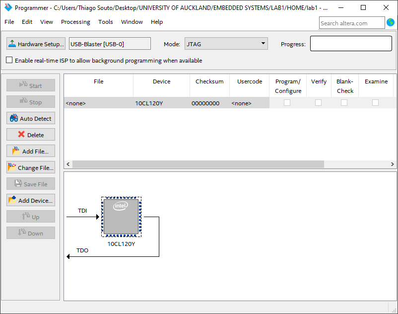
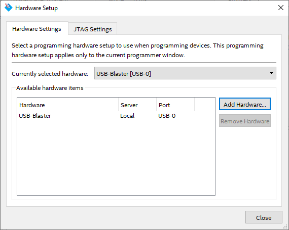
Click the “Hardware Setup” button to make sure the currently selected hardware is USB Blaster as shown in Figure 1 2. If this is not the case, select USB Blaster from the Available hardware items list, click the “Add Hardware” button and close the dialog. If USB Blaster is not present in the list, then the board may not be connected properly or your computer may not have the correct drivers installed.
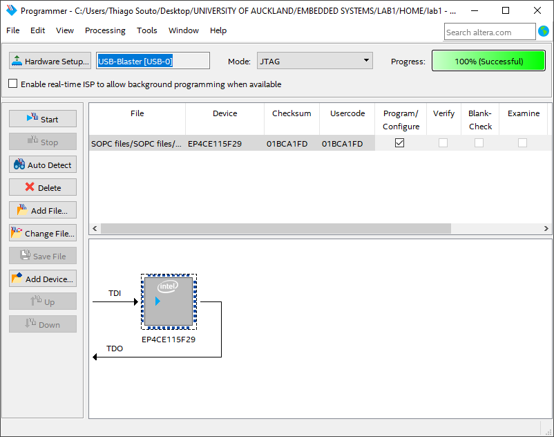
Click on the “Add File” or “Change File” button on the left of the Programmer dialog to include freq_relay_controller.sof and tick the box under "Program/Configure”. Then click the Start button to download the hardware design to the DE2 115 board. The progress of the download is displayed on the progress bar. Now you are ready to start the software implementation of the Nios II system.
# Introducing software to the system
The hardware design is ready and downloaded to the FGPA. However, the Nios II processor must be loaded with a program to execute.
# 2. Software implementation on the DE2 115 with dedicated hardware design
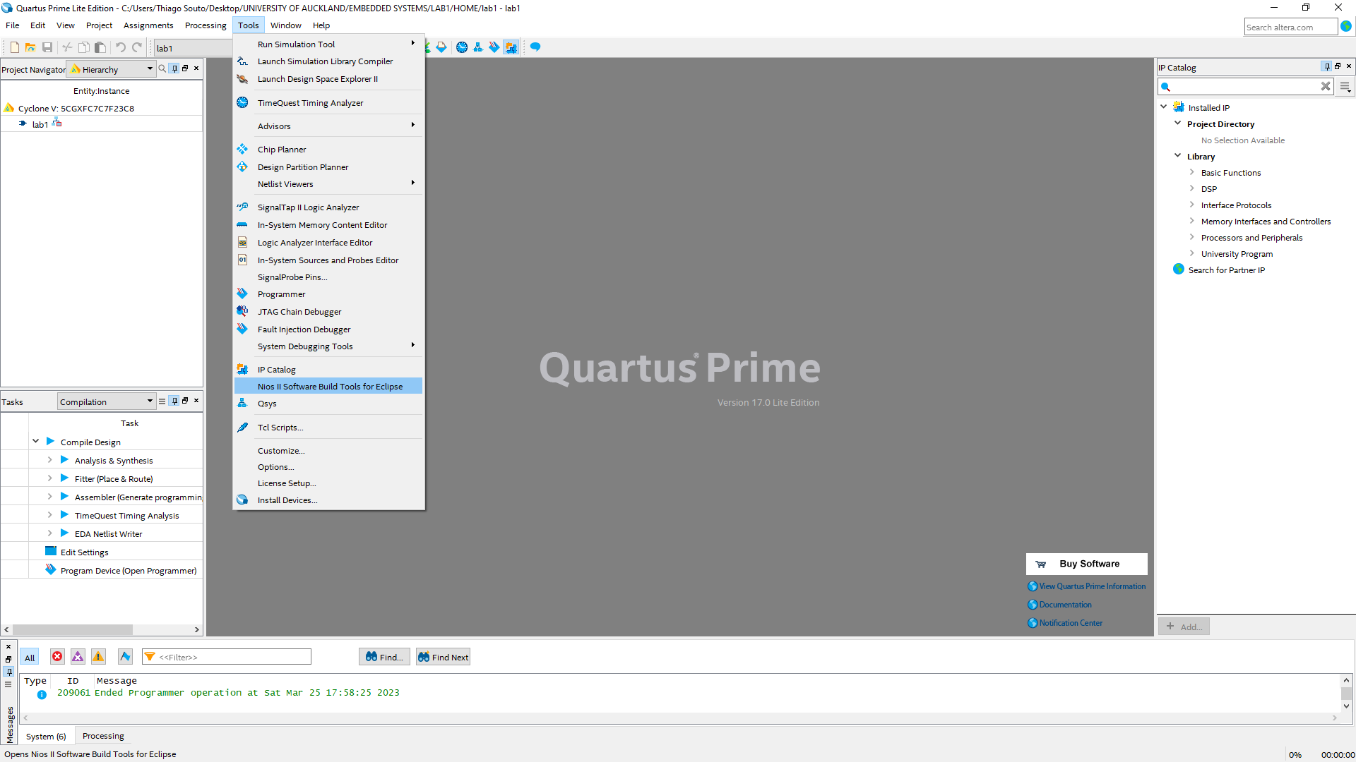
Developing software with Nios II IDE Software development for the Nios II platform can be performed using the Nios II Software Build Tools IDE (integrated development which is based on Eclipse. Start the Nios II IDE from the start menu. The main IDE window is illustrated in Figure 2 1.

# Construct an application with basic BSP
To use the Nios II IDE, you must first create a workspace. A workspace is used to store the current state of the IDE. It stores the currently opened projects and their associated configurations. When opening Eclipse for the first time, it will ask you to specify a workspace directory. You can also change the current workspace to an existing workspace or a new workspace using the File menu (File -->Switch Workspace). We will create a new workspace for this lab.
Browse and create a directory (named software) in the directory where you have placed the provided freq_relay_controller.sof and nios2.sopcinfo files and use this as the workspace directory.
TIP
Place the SOPC files on C: otherwise it will not accept the SOPC name due to spaces on the path.
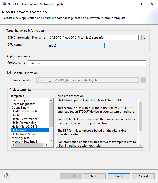
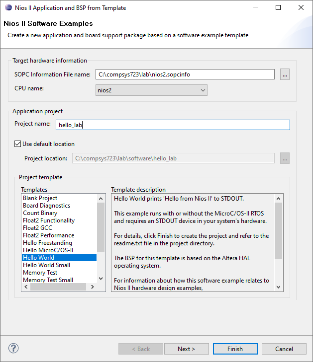
To create an application, select “File -->New -->Nios II Application and BSP from Template” from the main menu and perform the following steps as shown in Figure 2 3
- Choose
nios2.sopcinfofor the SOPC Information File name - Choose
nios2for the CPU name - Input
hello_labfor the Project name. - You should see “c: compsys723 lab software hello_lab” appear as the default project location
- Choose “Hello World” for the Project template
- Click “Next”.
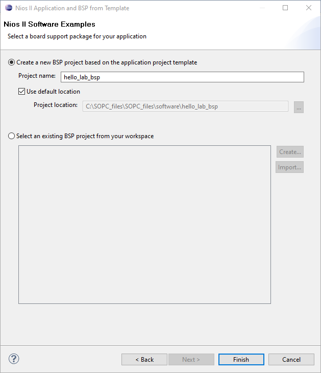
Use “hello_lab _bsp ” as the name of the BSP and use the default location provided.
Click “Finish” to generate the template Nios II application and corresponding BSP.
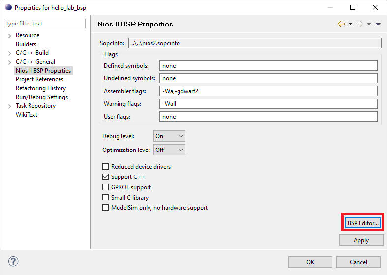
We have to specify where the program code will be stored this can either be on-chip memory, SDRAM, Flash memory, or SRAM). The relevant settings are shown in Figure 2 5
- Right-click on the BSP project named hello_lab_bsp
- Click on Properties
- Click on Nios II BSP Properties in the left pane.
- Select BSP Editor.
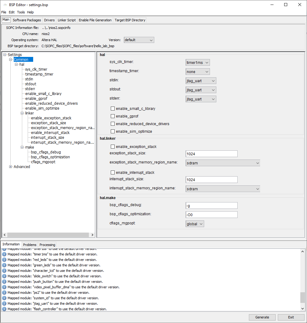
The settings of the BSP will be displayed, as shown in Figure 2 6. The settings tabs include the following:
- Main: options that configure the HAL, including the devices to use for standard input, output, and error output of the system
- Software packages: optional software packages required for the application, this includes packages that enable the use of compressed file systems.
- Drivers: drivers provided by Altera and other vendors are listed here.
- Linker Script: configuration of the linking phase of the compilation process in which the object files of the project are combined into a single executable which is loaded into memory.
- Enable File Generation: configuration of the by-product files which will be generated along with the BSP
- Targe t BSP directory: the structure of the BSP directory that will be generated.
We will configure several settings in the Main and Linker Script tabs and keep the default settings in the other tabs
In the Main tab, choose “Settings Common” in the left pane and follow the steps below which are also illustrated in Figure 2 7
- Select “jtag_uart” for stderr , stdin , and stdout . You might want to change these options in the future depending on your application, but we will leave it as the default (jtag_uart) for now. This will cause output from the program to be shown in the console in the Nios II IDE or the terminal program that is provided (name d: nios2-terminal ). Several character output devices can be selected, including uart character_lcd (the LCD on the board ), or jtag_uart (a shared connection with the USB BLASTER which uses the JTAG for communication).
- Select “ timer_1ms ” for the sys_clk_timer. This changes the frequency of the system timer to 1 KHz.
- Select “ SDRAM for:
- exception _stack _memory_region_name
- int errupt_stack_memory_region_name This uses the SDRAM for the stack when interrupts or exceptions occur while running a program
In the Linker Script tab, make sure “sdram” is selected as shown in Figure 2 8 for the following fields:
- .bss: stores uninitialized statically allocated variables T his includes all global arrays and variables as well as static variables declared locally in a function that are not initialized with a value
- .heap: the storage area for memory that is dynamically allocated using the malloc function call Dynamically allocated memory can be useful for implementing many data structures such as linked lists.
- .rodata: is used for constant, read-only data such as constant values that are defined with the define macro. For instance, #define ABC 100 will store a value of 100 in this section.
- .rwdata: stores initialized global and static variables which may be modified during program execution. For example, a local static variable with the following declaration: static int test = 20, will cause the test variable to be stored in this section, with an initial value of 20.
- .stack: this section is used for storing non-static local variables of a function. This includes the arguments passed to the function
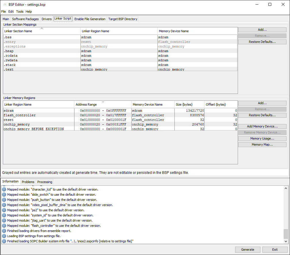
Click “Generate” to populate the settings and click “Exit” to return to the previous properties window shown in Figure 2 5
TIP
The other options in the BSP editor allow you to further customize the BSP for specific needs. For example, a developer would want to tick “Small C library” and /or un-tick "Support C++” to limit the memory usage on a system with a very constrained amount of available memory.
Also, choose onchip memory for .text.
# 3. Compile and run the first Nios II program in this lab
To build and run the Nios II program, perform the following:
Right-click on the hello_lab project and select “Build Project” to start compiling. You don’t need to do this for the BSP project as it is a dependency of the hello_lab project, so the BSP project will be built automatically if necessary (for instance when the BSP settings are modified
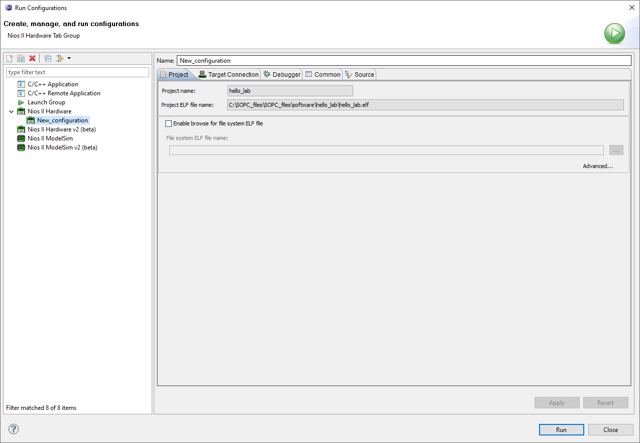
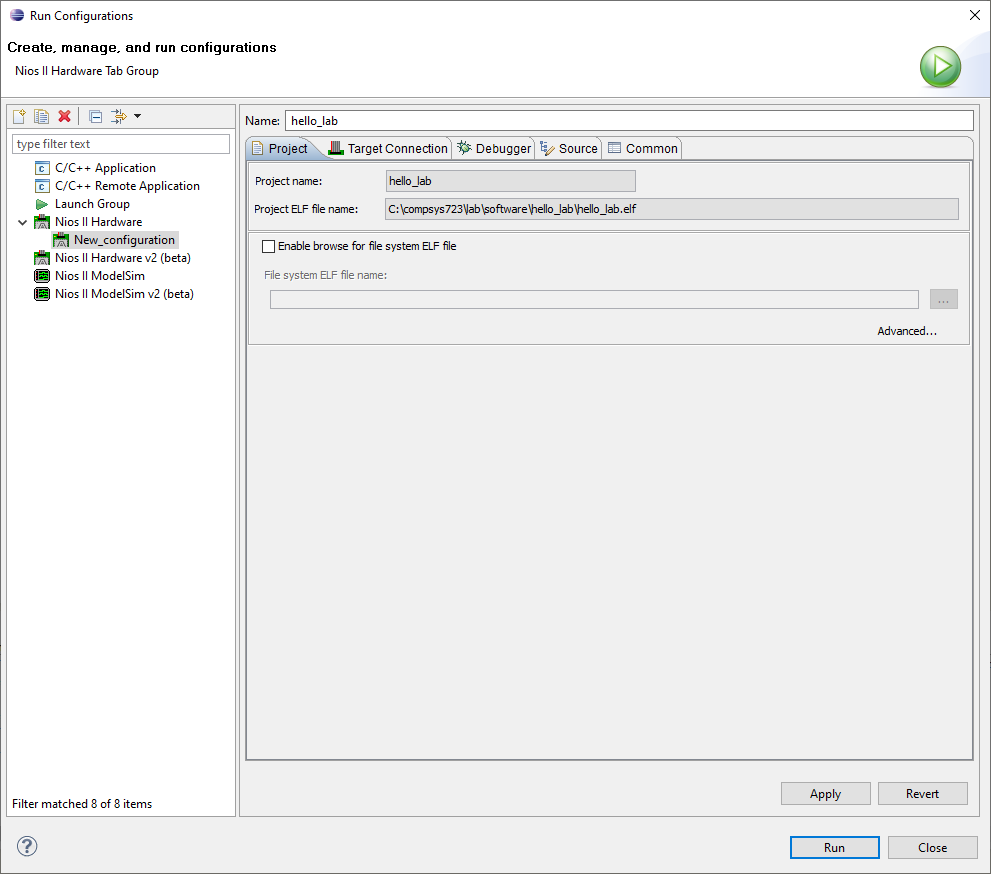
To run the application, click “Run” from the menu bar and select “Run Configurations”. Right-click on “ Nios II Hardware ”and select New” as shown in Figure 3 2.
Make sure the Project tab is selected and use the name “hello_lab” for this configuration. Make sure the project name is hello_lab by selecting it from the dropdown box.
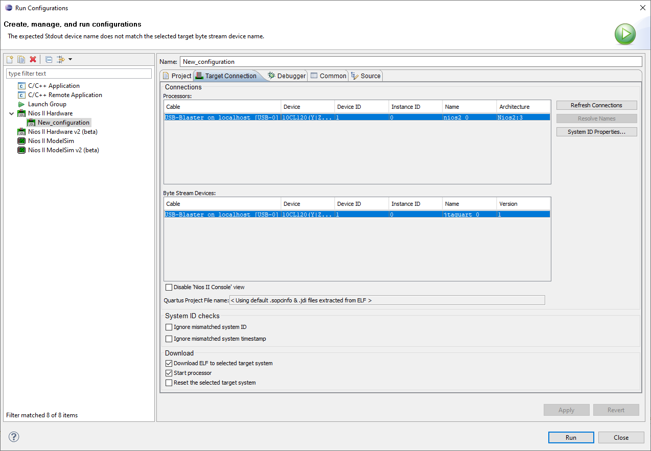
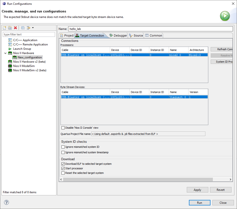
- Now change to the “ Target Connection ” tab. As shown in Figure 3 4, select USB Blaster for the Processor and Byte Stream Device. If USB Blaster is not displayed, make sure the board is connected to the computer with the provided SOF file correctly downloaded onto it and click Refresh. Now click “Run"** in the lower right corner. If the code in the project has changed, the project may be rebuilt before being loaded onto the processor.
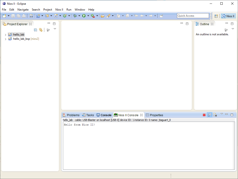
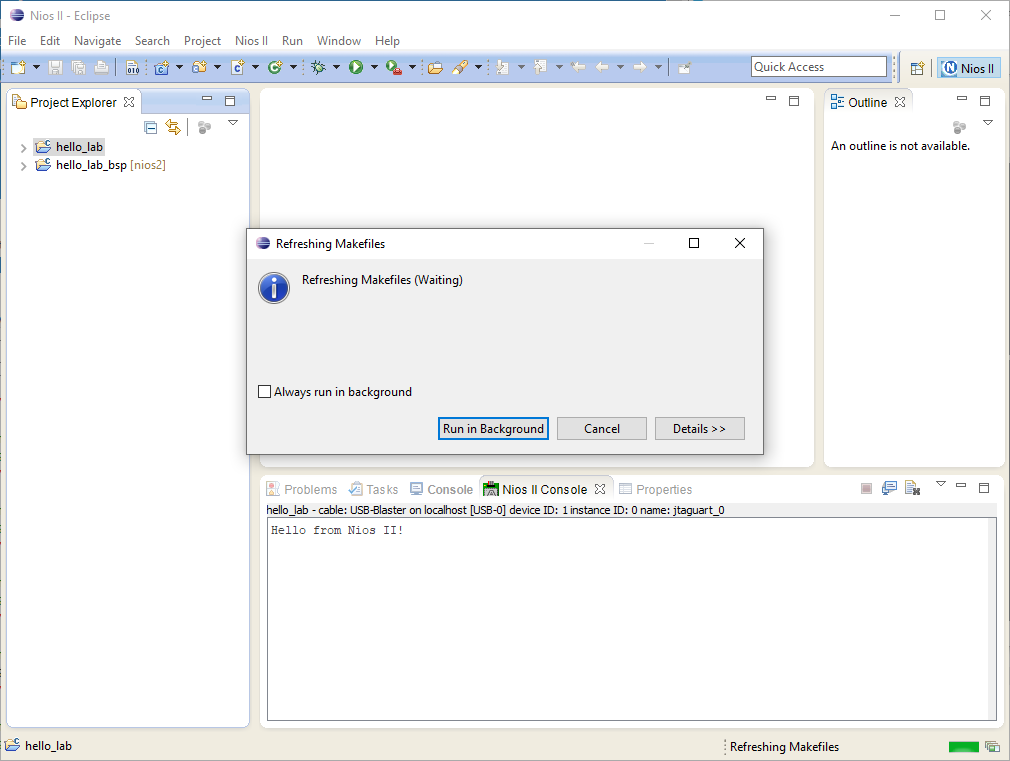
- You should soon be able to see the progress of the building and downloading process in the Console tab of the IDE as shown in Figure 3 5. “Hello from Nios will be displayed in the “Nios II Console” as shown in Figure 3 6 once the application has been downloaded and executed successfully. Click 🟥 to terminate the execution.
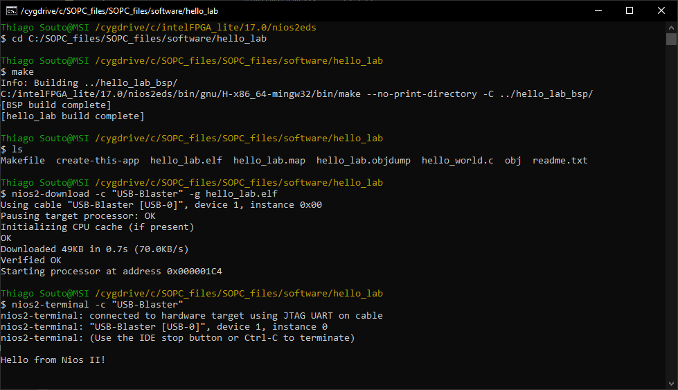
# Executing on the console
Thiago_Souto@MSI /cygdrive/c/SOPC_files/SOPC_files
$ cd C:/SOPC_files/SOPC_files/software/hello_lab

Thiago_Souto@MSI /cygdrive/c/SOPC_files/SOPC_files/software/hello_lab
$ make
Info: Building ../hello_lab_bsp/
C:/intelFPGA_lite/17.0/nios2eds/bin/gnu/H-x86_64-mingw32/bin/make --no-print-directory -C ../hello_lab_bsp/
[BSP build complete]
[hello_lab build complete]

Thiago_Souto@MSI /cygdrive/c/SOPC_files/SOPC_files/software/hello_lab
$ ls
Makefile  create-this-app  hello_lab.elf  hello_lab.map  hello_lab.objdump  hello_world.c  obj  readme.txt

Thiago_Souto@MSI /cygdrive/c/SOPC_files/SOPC_files/software/hello_lab
$ nios2-download -c "USB-Blaster" -g hello_lab.elf
Using cable "USB-Blaster [USB-0]", device 1, instance 0x00
Pausing target processor: OK
Initializing CPU cache (if present)
OK
Downloaded 49KB in 0.6s (81.6KB/s)
Verified OK
Starting processor at address 0x08000000

Thiago_Souto@MSI /cygdrive/c/SOPC_files/SOPC_files/software/hello_lab
$ nios2-terminal -c "USB-Blaster"
nios2-terminal: connected to hardware target using JTAG UART on cable
nios2-terminal: "USB-Blaster [USB-0]", device 1, instance 0
nios2-terminal: (Use the IDE stop button or Ctrl-C to terminate)
2
3
4
5
6
7
8
9
10
11
12
13
14
15
16
17
18
19
20
21
22
23
24
25
26
27
28
29
The Shell is located on C:\intelFPGA_lite\17.0\nios2eds
TIP
jtagconfig
This command will display a list of all the JTAG cables that are currently connected to your system, along with their status and other details. The output of this command should help you determine if the JTAG cable you are trying to use is properly connected and recognized by your system.
If the JTAG cable you want to use is not listed by the jtagconfig command, it is possible that the cable is not properly connected or not supported by your system. You may need to check the cable's connections and compatibility or use a different cable that is known to be compatible with your system.
# COMPSYS723 Lab Manual - Application Programming with FreeRTOS on DE2 115
# Background Information:
The system was designed using the Qsys tool which is a part of the Quartus II design package. Qsys is similar to SOPC builder a tool that was bundled with earlier versions of Quartus which you may have encountered previously. This tool provides a graphical interface for creating systems on programmable chips.
These systems typically contain components that allow you to control various things, such as the switches, LEDs and buttons on the DE2 115 board, or the off-chip SRAM/SDRAM. The hardware components of the Nios II system can be categorized into several groups, according to how they are used in the practice.
- Memory Components: these can be read only (ROM), random access (RAM) or other types according to their characteristics.
- Input/Output (I/O) peripherals An embedded system interacts with its environment through input/output peripherals. You can read from/write to these peripherals either by accessing memory-mapped registers directly or by calling available APIs (application programming interfaces) in the board support package.
- Integrated peripherals These are peripherals that are integrated into the Nios II processor. An example of this is the timer peripheral, which can be used after setting up its parameters. A hardware timer is often required by system software (such as a real-time operating system).
We will make use of these peripherals in the following sections.
# Part 1 - Setting up a new workspace and project
Download the lab folder from Canvas and unzip it to a sensible location
Create a new folder that will serve as the location for your project work and copy
freq_relay_controller.sofandnios2.sopcinfointo the folder. Choose a directory using the following guidelines:
There should be no spaces in the name of the directory. For instance, paths such as “c:\compsys 723\lab” or “ compsys723\lab test 1” are not acceptable.
The NIOS II Eclipse software uses absolute paths in project files. As a result, your project should always be on the same path. If the path of the project directory has changed, then you will need to import the project into your workspace again.
You can use H: drive to avoid access issues that may otherwise occur, however, this may increase your login/logout times as H: drive is synced with the university network. You can also use a USB flash drive. You can also use your own computer.
“C:\compsys723\lab” is used in this document
Start the Nios II IDE from the start menu.
A dialog window will appear, asking you to specify a workspace Browse to the folder you created in step 2.
A workspace is used to store the current state of the IDE. It stores the currently opened projects and their associated configurations. You can also change the current workspace to an existing workspace or a new workspace using the File menu (File -->Switch Workspace)
- To create an application, select “ File -->New-->Nios II Application and BSP from Template ” from the main menu and perform the following steps:
Choose nios2.sopcinfo for the SOPC Information File name.
Choose nios2 for the CPU name
Input hello_lab for the Project name.
You should see “c:\compsys723\lab\software\hello_lab” appear as the default project location. (or something similar)
Choose “Hello World” for the Project template.
Click “Next”.
- Compile and run the first Nios II program in this lab
To build and run the Nios II program, perform the following:
- Right-click on the hello_lab project and select “ Build Project ” to start compiling.
You don’t need to do this for the BSP project as it is a dependency of the hello_lab project, so the BSP project will be built automatically if necessary (for instance when the BSP settings are modified).
To run the application, click “ Run ” from the menu bar and select “ Run Configurations ”. Right-click on “ Nios II Hardware ” and select ” New ”.
Make sure the Project tab is selected and use the name “hello_lab” for this configuration. Make sure the project name is hello_lab by selecting it from the dropdown box.
Now change to the** “Target Connection”** tab. Select “USB--Blaster” for the Processor and Byte Stream Devices. If USB--Blaster is not displayed, make sure the board is connected to the computer with the provided SOF file correctly downloaded onto it and click Refresh.
Now click “Run” in the lower right corner. If the code in the project has changed, the project may be rebuilt before being loaded onto the processor.
- You should be able to see the progress of the building and downloading process in the Console tab of the IDE.
“Hello from Nios II” will be displayed in the “Nios II Console”, once the application has been downloaded and executed successfully. Click to terminate the execution.
- You may ignore mismatched system IDs and timestamps with the target platform when running your program.
TIP
Remember to upload the BSP and the freq_relay_controller.sof file like here
Result:
# What’s going on?
When we created the project with a BSP, two folders can be seen in the project navigator window. The first folder is your software, in this case, the hello world program. Any c source code you write goes into this folder.
The second folder is the BSP, or Board Support Package. When we specified the .sopcinfo file, the SBT
automatically generated this folder and all the things inside it. This BSP contains Hardware abstraction layer (HAL) that is specific to our system.
When we write application software, we utilize the HAL to manipulate the different hardware components. It is very difficult to write software for hardware directly, so the BSP includes low-level routines to control hardware and exposes APIs to allow easier control of hardware in a user application.
The BSP is platform dependent. The HAL is also responsible for initializing the system and devices before the user application is run.
The software the combination of the BSP and application logic) is stored in memory. When the processor is reset, it begins executing from a specific location in the memory Qsys generates a .sopcinfo file which includes information about the Nios II system. This information includes the processor type, available hardware and internal interconnections.
# Part 2 - Using some of the peripherals
In this section, we will introduce to you the use of the peripherals in your system, such as the LEDs, SWITCHES and LCD. We’ll also have a look at system.h, which is an integral part of the board support package.
# Accessing components in the Nios II system
As mentioned previously, nios2.sopcinfo contains information about the components of the Nios II system.
Each component is described with a set of fields including:
The address of the component: this is the base address to which the component is mapped in the processor’s address space.
The IRQ of the component: indicates the interrupt number of the component. This is only applicable to components that generate interrupts.
Other information.
However, even though it is stored in clear text, nios2.sopcinfo is not programmer friendly. The system.h file, which is produced during the BSP build, presents the same information in a more readable manner. You can find system.h in the hello_lab_bsp.
The system.h file consists of entries in the form of symbolic constants which are defined with the #define macro. For instance, the base address of the timer1ms component (0x43040) is assigned with a symbolic name of “ TIMER1MS_BASE ”. You can use TIMER1MS_BASE in your application code instead of a hardcoded base address value. This increases the portability of the program from one configuration to another (in cases where the names of the modules are the same in both configurations but the base address values may differ).
The base address can be considered a hardware component’s identifier. A component is accessed by using its base address as an argument to function calls provided by the BSP.
To use the symbolic constants in the system.h file, add #include <system> to the beginning of your application code (in this case, the hello_world.c file within the hello_lab project).
# System.h
system.h
#ifndef __SYSTEM_H_
#define __SYSTEM_H_

/* Include definitions from linker script generator */
#include "linker.h"


/*
 * CPU configuration
 *
 */

#define ALT_CPU_ARCHITECTURE "altera_nios2_qsys"
#define ALT_CPU_BIG_ENDIAN 0
#define ALT_CPU_BREAK_ADDR 0x00042820
#define ALT_CPU_CPU_FREQ 100000000u
#define ALT_CPU_CPU_ID_SIZE 1
#define ALT_CPU_CPU_ID_VALUE 0x00000000
#define ALT_CPU_CPU_IMPLEMENTATION "fast"
#define ALT_CPU_DATA_ADDR_WIDTH 0x1c
#define ALT_CPU_DCACHE_LINE_SIZE 32
#define ALT_CPU_DCACHE_LINE_SIZE_LOG2 5
#define ALT_CPU_DCACHE_SIZE 2048
#define ALT_CPU_EXCEPTION_ADDR 0x00000020
#define ALT_CPU_FLUSHDA_SUPPORTED
#define ALT_CPU_FREQ 100000000
#define ALT_CPU_HARDWARE_DIVIDE_PRESENT 1
#define ALT_CPU_HARDWARE_MULTIPLY_PRESENT 1
#define ALT_CPU_HARDWARE_MULX_PRESENT 0
#define ALT_CPU_HAS_DEBUG_CORE 1
#define ALT_CPU_HAS_DEBUG_STUB
#define ALT_CPU_HAS_JMPI_INSTRUCTION
#define ALT_CPU_ICACHE_LINE_SIZE 32
#define ALT_CPU_ICACHE_LINE_SIZE_LOG2 5
#define ALT_CPU_ICACHE_SIZE 4096
#define ALT_CPU_INITDA_SUPPORTED
#define ALT_CPU_INST_ADDR_WIDTH 0x19
#define ALT_CPU_NAME "nios2"
#define ALT_CPU_NUM_OF_SHADOW_REG_SETS 0
#define ALT_CPU_RESET_ADDR 0x01000000


/*
 * CPU configuration (with legacy prefix - don't use these anymore)
 *
 */

#define NIOS2_BIG_ENDIAN 0
#define NIOS2_BREAK_ADDR 0x00042820
#define NIOS2_CPU_FREQ 100000000u
#define NIOS2_CPU_ID_SIZE 1
#define NIOS2_CPU_ID_VALUE 0x00000000
#define NIOS2_CPU_IMPLEMENTATION "fast"
#define NIOS2_DATA_ADDR_WIDTH 0x1c
#define NIOS2_DCACHE_LINE_SIZE 32
#define NIOS2_DCACHE_LINE_SIZE_LOG2 5
#define NIOS2_DCACHE_SIZE 2048
#define NIOS2_EXCEPTION_ADDR 0x00000020
#define NIOS2_FLUSHDA_SUPPORTED
#define NIOS2_HARDWARE_DIVIDE_PRESENT 1
#define NIOS2_HARDWARE_MULTIPLY_PRESENT 1
#define NIOS2_HARDWARE_MULX_PRESENT 0
#define NIOS2_HAS_DEBUG_CORE 1
#define NIOS2_HAS_DEBUG_STUB
#define NIOS2_HAS_JMPI_INSTRUCTION
#define NIOS2_ICACHE_LINE_SIZE 32
#define NIOS2_ICACHE_LINE_SIZE_LOG2 5
#define NIOS2_ICACHE_SIZE 4096
#define NIOS2_INITDA_SUPPORTED
#define NIOS2_INST_ADDR_WIDTH 0x19
#define NIOS2_NUM_OF_SHADOW_REG_SETS 0
#define NIOS2_RESET_ADDR 0x01000000


/*
 * Define for each module class mastered by the CPU
 *
 */

#define __ALTERA_AVALON_JTAG_UART
#define __ALTERA_AVALON_LCD_16207
#define __ALTERA_AVALON_NEW_SDRAM_CONTROLLER
#define __ALTERA_AVALON_ONCHIP_MEMORY2
#define __ALTERA_AVALON_PIO
#define __ALTERA_AVALON_SYSID_QSYS
#define __ALTERA_AVALON_TIMER
#define __ALTERA_AVALON_UART
#define __ALTERA_GENERIC_TRISTATE_CONTROLLER
#define __ALTERA_NIOS2_QSYS
#define __ALTERA_UP_AVALON_PS2
#define __ALTERA_UP_AVALON_SRAM
#define __ALTERA_UP_AVALON_VIDEO_CHARACTER_BUFFER_WITH_DMA
#define __ALTERA_UP_AVALON_VIDEO_PIXEL_BUFFER_DMA
#define __FREQUENCY_ANALYSER
#define __SEVEN_SEG


/*
 * System configuration
 *
 */

#define ALT_DEVICE_FAMILY "Cyclone IV E"
#define ALT_IRQ_BASE NULL
#define ALT_LEGACY_INTERRUPT_API_PRESENT
#define ALT_LOG_PORT "/dev/null"
#define ALT_LOG_PORT_BASE 0x0
#define ALT_LOG_PORT_DEV null
#define ALT_LOG_PORT_TYPE ""
#define ALT_NUM_EXTERNAL_INTERRUPT_CONTROLLERS 0
#define ALT_NUM_INTERNAL_INTERRUPT_CONTROLLERS 1
#define ALT_NUM_INTERRUPT_CONTROLLERS 1
#define ALT_STDERR "/dev/jtag_uart"
#define ALT_STDERR_BASE 0x430f8
#define ALT_STDERR_DEV jtag_uart
#define ALT_STDERR_IS_JTAG_UART
#define ALT_STDERR_PRESENT
#define ALT_STDERR_TYPE "altera_avalon_jtag_uart"
#define ALT_STDIN "/dev/jtag_uart"
#define ALT_STDIN_BASE 0x430f8
#define ALT_STDIN_DEV jtag_uart
#define ALT_STDIN_IS_JTAG_UART
#define ALT_STDIN_PRESENT
#define ALT_STDIN_TYPE "altera_avalon_jtag_uart"
#define ALT_STDOUT "/dev/jtag_uart"
#define ALT_STDOUT_BASE 0x430f8
#define ALT_STDOUT_DEV jtag_uart
#define ALT_STDOUT_IS_JTAG_UART
#define ALT_STDOUT_PRESENT
#define ALT_STDOUT_TYPE "altera_avalon_jtag_uart"
#define ALT_SYSTEM_NAME "nios2"


/*
 * character_lcd configuration
 *
 */

#define ALT_MODULE_CLASS_character_lcd altera_avalon_lcd_16207
#define CHARACTER_LCD_BASE 0x430a0
#define CHARACTER_LCD_IRQ -1
#define CHARACTER_LCD_IRQ_INTERRUPT_CONTROLLER_ID -1
#define CHARACTER_LCD_NAME "/dev/character_lcd"
#define CHARACTER_LCD_SPAN 16
#define CHARACTER_LCD_TYPE "altera_avalon_lcd_16207"


/*
 * flash_controller configuration
 *
 */

#define ALT_MODULE_CLASS_flash_controller altera_generic_tristate_controller
#define FLASH_CONTROLLER_BASE 0x1000000
#define FLASH_CONTROLLER_HOLD_VALUE 60
#define FLASH_CONTROLLER_IRQ -1
#define FLASH_CONTROLLER_IRQ_INTERRUPT_CONTROLLER_ID -1
#define FLASH_CONTROLLER_NAME "/dev/flash_controller"
#define FLASH_CONTROLLER_SETUP_VALUE 60
#define FLASH_CONTROLLER_SIZE 8388608u
#define FLASH_CONTROLLER_SPAN 8388608
#define FLASH_CONTROLLER_TIMING_UNITS "ns"
#define FLASH_CONTROLLER_TYPE "altera_generic_tristate_controller"
#define FLASH_CONTROLLER_WAIT_VALUE 160


/*
 * frequency_analyser configuration
 *
 */

#define ALT_MODULE_CLASS_frequency_analyser frequency_analyser
#define FREQUENCY_ANALYSER_BASE 0x43100
#define FREQUENCY_ANALYSER_IRQ 7
#define FREQUENCY_ANALYSER_IRQ_INTERRUPT_CONTROLLER_ID 0
#define FREQUENCY_ANALYSER_NAME "/dev/frequency_analyser"
#define FREQUENCY_ANALYSER_SPAN 4
#define FREQUENCY_ANALYSER_TYPE "frequency_analyser"


/*
 * green_leds configuration
 *
 */

#define ALT_MODULE_CLASS_green_leds altera_avalon_pio
#define GREEN_LEDS_BASE 0x43080
#define GREEN_LEDS_BIT_CLEARING_EDGE_REGISTER 0
#define GREEN_LEDS_BIT_MODIFYING_OUTPUT_REGISTER 1
#define GREEN_LEDS_CAPTURE 0
#define GREEN_LEDS_DATA_WIDTH 9
#define GREEN_LEDS_DO_TEST_BENCH_WIRING 0
#define GREEN_LEDS_DRIVEN_SIM_VALUE 0
#define GREEN_LEDS_EDGE_TYPE "NONE"
#define GREEN_LEDS_FREQ 100000000
#define GREEN_LEDS_HAS_IN 0
#define GREEN_LEDS_HAS_OUT 1
#define GREEN_LEDS_HAS_TRI 0
#define GREEN_LEDS_IRQ -1
#define GREEN_LEDS_IRQ_INTERRUPT_CONTROLLER_ID -1
#define GREEN_LEDS_IRQ_TYPE "NONE"
#define GREEN_LEDS_NAME "/dev/green_leds"
#define GREEN_LEDS_RESET_VALUE 0
#define GREEN_LEDS_SPAN 32
#define GREEN_LEDS_TYPE "altera_avalon_pio"


/*
 * hal configuration
 *
 */

#define ALT_MAX_FD 32
#define ALT_SYS_CLK TIMER1MS
#define ALT_TIMESTAMP_CLK none


/*
 * jtag_uart configuration
 *
 */

#define ALT_MODULE_CLASS_jtag_uart altera_avalon_jtag_uart
#define JTAG_UART_BASE 0x430f8
#define JTAG_UART_IRQ 5
#define JTAG_UART_IRQ_INTERRUPT_CONTROLLER_ID 0
#define JTAG_UART_NAME "/dev/jtag_uart"
#define JTAG_UART_READ_DEPTH 512
#define JTAG_UART_READ_THRESHOLD 8
#define JTAG_UART_SPAN 8
#define JTAG_UART_TYPE "altera_avalon_jtag_uart"
#define JTAG_UART_WRITE_DEPTH 512
#define JTAG_UART_WRITE_THRESHOLD 8


/*
 * onchip_memory configuration
 *
 */

#define ALT_MODULE_CLASS_onchip_memory altera_avalon_onchip_memory2
#define ONCHIP_MEMORY_ALLOW_IN_SYSTEM_MEMORY_CONTENT_EDITOR 0
#define ONCHIP_MEMORY_ALLOW_MRAM_SIM_CONTENTS_ONLY_FILE 0
#define ONCHIP_MEMORY_BASE 0x0
#define ONCHIP_MEMORY_CONTENTS_INFO ""
#define ONCHIP_MEMORY_DUAL_PORT 0
#define ONCHIP_MEMORY_GUI_RAM_BLOCK_TYPE "AUTO"
#define ONCHIP_MEMORY_INIT_CONTENTS_FILE "nios2_onchip_memory"
#define ONCHIP_MEMORY_INIT_MEM_CONTENT 1
#define ONCHIP_MEMORY_INSTANCE_ID "NONE"
#define ONCHIP_MEMORY_IRQ -1
#define ONCHIP_MEMORY_IRQ_INTERRUPT_CONTROLLER_ID -1
#define ONCHIP_MEMORY_NAME "/dev/onchip_memory"
#define ONCHIP_MEMORY_NON_DEFAULT_INIT_FILE_ENABLED 0
#define ONCHIP_MEMORY_RAM_BLOCK_TYPE "AUTO"
#define ONCHIP_MEMORY_READ_DURING_WRITE_MODE "DONT_CARE"
#define ONCHIP_MEMORY_SINGLE_CLOCK_OP 0
#define ONCHIP_MEMORY_SIZE_MULTIPLE 1
#define ONCHIP_MEMORY_SIZE_VALUE 204800
#define ONCHIP_MEMORY_SPAN 204800
#define ONCHIP_MEMORY_TYPE "altera_avalon_onchip_memory2"
#define ONCHIP_MEMORY_WRITABLE 1


/*
 * ps2 configuration
 *
 */

#define ALT_MODULE_CLASS_ps2 altera_up_avalon_ps2
#define PS2_BASE 0x430e0
#define PS2_IRQ 2
#define PS2_IRQ_INTERRUPT_CONTROLLER_ID 0
#define PS2_NAME "/dev/ps2"
#define PS2_SPAN 8
#define PS2_TYPE "altera_up_avalon_ps2"


/*
 * push_button configuration
 *
 */

#define ALT_MODULE_CLASS_push_button altera_avalon_pio
#define PUSH_BUTTON_BASE 0x430c0
#define PUSH_BUTTON_BIT_CLEARING_EDGE_REGISTER 1
#define PUSH_BUTTON_BIT_MODIFYING_OUTPUT_REGISTER 0
#define PUSH_BUTTON_CAPTURE 1
#define PUSH_BUTTON_DATA_WIDTH 3
#define PUSH_BUTTON_DO_TEST_BENCH_WIRING 0
#define PUSH_BUTTON_DRIVEN_SIM_VALUE 0
#define PUSH_BUTTON_EDGE_TYPE "FALLING"
#define PUSH_BUTTON_FREQ 100000000
#define PUSH_BUTTON_HAS_IN 1
#define PUSH_BUTTON_HAS_OUT 0
#define PUSH_BUTTON_HAS_TRI 0
#define PUSH_BUTTON_IRQ 1
#define PUSH_BUTTON_IRQ_INTERRUPT_CONTROLLER_ID 0
#define PUSH_BUTTON_IRQ_TYPE "EDGE"
#define PUSH_BUTTON_NAME "/dev/push_button"
#define PUSH_BUTTON_RESET_VALUE 0
#define PUSH_BUTTON_SPAN 16
#define PUSH_BUTTON_TYPE "altera_avalon_pio"


/*
 * red_leds configuration
 *
 */

#define ALT_MODULE_CLASS_red_leds altera_avalon_pio
#define RED_LEDS_BASE 0x43060
#define RED_LEDS_BIT_CLEARING_EDGE_REGISTER 0
#define RED_LEDS_BIT_MODIFYING_OUTPUT_REGISTER 1
#define RED_LEDS_CAPTURE 0
#define RED_LEDS_DATA_WIDTH 18
#define RED_LEDS_DO_TEST_BENCH_WIRING 0
#define RED_LEDS_DRIVEN_SIM_VALUE 0
#define RED_LEDS_EDGE_TYPE "NONE"
#define RED_LEDS_FREQ 100000000
#define RED_LEDS_HAS_IN 0
#define RED_LEDS_HAS_OUT 1
#define RED_LEDS_HAS_TRI 0
#define RED_LEDS_IRQ -1
#define RED_LEDS_IRQ_INTERRUPT_CONTROLLER_ID -1
#define RED_LEDS_IRQ_TYPE "NONE"
#define RED_LEDS_NAME "/dev/red_leds"
#define RED_LEDS_RESET_VALUE 0
#define RED_LEDS_SPAN 32
#define RED_LEDS_TYPE "altera_avalon_pio"


/*
 * sdram configuration
 *
 */

#define ALT_MODULE_CLASS_sdram altera_avalon_new_sdram_controller
#define SDRAM_BASE 0x8000000
#define SDRAM_CAS_LATENCY 3
#define SDRAM_CONTENTS_INFO
#define SDRAM_INIT_NOP_DELAY 0.0
#define SDRAM_INIT_REFRESH_COMMANDS 2
#define SDRAM_IRQ -1
#define SDRAM_IRQ_INTERRUPT_CONTROLLER_ID -1
#define SDRAM_IS_INITIALIZED 1
#define SDRAM_NAME "/dev/sdram"
#define SDRAM_POWERUP_DELAY 100.0
#define SDRAM_REFRESH_PERIOD 15.625
#define SDRAM_REGISTER_DATA_IN 1
#define SDRAM_SDRAM_ADDR_WIDTH 0x19
#define SDRAM_SDRAM_BANK_WIDTH 2
#define SDRAM_SDRAM_COL_WIDTH 10
#define SDRAM_SDRAM_DATA_WIDTH 32
#define SDRAM_SDRAM_NUM_BANKS 4
#define SDRAM_SDRAM_NUM_CHIPSELECTS 1
#define SDRAM_SDRAM_ROW_WIDTH 13
#define SDRAM_SHARED_DATA 0
#define SDRAM_SIM_MODEL_BASE 0
#define SDRAM_SPAN 134217728
#define SDRAM_STARVATION_INDICATOR 0
#define SDRAM_TRISTATE_BRIDGE_SLAVE ""
#define SDRAM_TYPE "altera_avalon_new_sdram_controller"
#define SDRAM_T_AC 5.5
#define SDRAM_T_MRD 3
#define SDRAM_T_RCD 20.0
#define SDRAM_T_RFC 70.0
#define SDRAM_T_RP 20.0
#define SDRAM_T_WR 14.0


/*
 * seven_seg configuration
 *
 */

#define ALT_MODULE_CLASS_seven_seg seven_seg
#define SEVEN_SEG_BASE 0x43104
#define SEVEN_SEG_IRQ -1
#define SEVEN_SEG_IRQ_INTERRUPT_CONTROLLER_ID -1
#define SEVEN_SEG_NAME "/dev/seven_seg"
#define SEVEN_SEG_SPAN 4
#define SEVEN_SEG_TYPE "seven_seg"


/*
 * slide_switch configuration
 *
 */

#define ALT_MODULE_CLASS_slide_switch altera_avalon_pio
#define SLIDE_SWITCH_BASE 0x430b0
#define SLIDE_SWITCH_BIT_CLEARING_EDGE_REGISTER 0
#define SLIDE_SWITCH_BIT_MODIFYING_OUTPUT_REGISTER 0
#define SLIDE_SWITCH_CAPTURE 0
#define SLIDE_SWITCH_DATA_WIDTH 18
#define SLIDE_SWITCH_DO_TEST_BENCH_WIRING 0
#define SLIDE_SWITCH_DRIVEN_SIM_VALUE 0
#define SLIDE_SWITCH_EDGE_TYPE "NONE"
#define SLIDE_SWITCH_FREQ 100000000
#define SLIDE_SWITCH_HAS_IN 1
#define SLIDE_SWITCH_HAS_OUT 0
#define SLIDE_SWITCH_HAS_TRI 0
#define SLIDE_SWITCH_IRQ -1
#define SLIDE_SWITCH_IRQ_INTERRUPT_CONTROLLER_ID -1
#define SLIDE_SWITCH_IRQ_TYPE "NONE"
#define SLIDE_SWITCH_NAME "/dev/slide_switch"
#define SLIDE_SWITCH_RESET_VALUE 0
#define SLIDE_SWITCH_SPAN 16
#define SLIDE_SWITCH_TYPE "altera_avalon_pio"


/*
 * sram configuration
 *
 */

#define ALT_MODULE_CLASS_sram altera_up_avalon_sram
#define SRAM_BASE 0x200000
#define SRAM_IRQ -1
#define SRAM_IRQ_INTERRUPT_CONTROLLER_ID -1
#define SRAM_NAME "/dev/sram"
#define SRAM_SPAN 2097152
#define SRAM_TYPE "altera_up_avalon_sram"


/*
 * system_id configuration
 *
 */

#define ALT_MODULE_CLASS_system_id altera_avalon_sysid_qsys
#define SYSTEM_ID_BASE 0x430f0
#define SYSTEM_ID_ID 7
#define SYSTEM_ID_IRQ -1
#define SYSTEM_ID_IRQ_INTERRUPT_CONTROLLER_ID -1
#define SYSTEM_ID_NAME "/dev/system_id"
#define SYSTEM_ID_SPAN 8
#define SYSTEM_ID_TIMESTAMP 1393900972
#define SYSTEM_ID_TYPE "altera_avalon_sysid_qsys"


/*
 * timer1ms configuration
 *
 */

#define ALT_MODULE_CLASS_timer1ms altera_avalon_timer
#define TIMER1MS_ALWAYS_RUN 0
#define TIMER1MS_BASE 0x43040
#define TIMER1MS_COUNTER_SIZE 32
#define TIMER1MS_FIXED_PERIOD 0
#define TIMER1MS_FREQ 100000000
#define TIMER1MS_IRQ 0
#define TIMER1MS_IRQ_INTERRUPT_CONTROLLER_ID 0
#define TIMER1MS_LOAD_VALUE 99999
#define TIMER1MS_MULT 0.001
#define TIMER1MS_NAME "/dev/timer1ms"
#define TIMER1MS_PERIOD 1
#define TIMER1MS_PERIOD_UNITS "ms"
#define TIMER1MS_RESET_OUTPUT 0
#define TIMER1MS_SNAPSHOT 1
#define TIMER1MS_SPAN 32
#define TIMER1MS_TICKS_PER_SEC 1000.0
#define TIMER1MS_TIMEOUT_PULSE_OUTPUT 0
#define TIMER1MS_TYPE "altera_avalon_timer"


/*
 * timer1us configuration
 *
 */

#define ALT_MODULE_CLASS_timer1us altera_avalon_timer
#define TIMER1US_ALWAYS_RUN 0
#define TIMER1US_BASE 0x43020
#define TIMER1US_COUNTER_SIZE 32
#define TIMER1US_FIXED_PERIOD 0
#define TIMER1US_FREQ 100000000
#define TIMER1US_IRQ 6
#define TIMER1US_IRQ_INTERRUPT_CONTROLLER_ID 0
#define TIMER1US_LOAD_VALUE 99
#define TIMER1US_MULT 1.0E-6
#define TIMER1US_NAME "/dev/timer1us"
#define TIMER1US_PERIOD 1
#define TIMER1US_PERIOD_UNITS "us"
#define TIMER1US_RESET_OUTPUT 0
#define TIMER1US_SNAPSHOT 1
#define TIMER1US_SPAN 32
#define TIMER1US_TICKS_PER_SEC 1000000.0
#define TIMER1US_TIMEOUT_PULSE_OUTPUT 0
#define TIMER1US_TYPE "altera_avalon_timer"


/*
 * uart configuration
 *
 */

#define ALT_MODULE_CLASS_uart altera_avalon_uart
#define UART_BASE 0x43000
#define UART_BAUD 115200
#define UART_DATA_BITS 8
#define UART_FIXED_BAUD 1
#define UART_FREQ 100000000
#define UART_IRQ 3
#define UART_IRQ_INTERRUPT_CONTROLLER_ID 0
#define UART_NAME "/dev/uart"
#define UART_PARITY 'N'
#define UART_SIM_CHAR_STREAM ""
#define UART_SIM_TRUE_BAUD 0
#define UART_SPAN 32
#define UART_STOP_BITS 1
#define UART_SYNC_REG_DEPTH 2
#define UART_TYPE "altera_avalon_uart"
#define UART_USE_CTS_RTS 0
#define UART_USE_EOP_REGISTER 0


/*
 * video_character_buffer_with_dma_avalon_char_buffer_slave configuration
 *
 */

#define ALT_MODULE_CLASS_video_character_buffer_with_dma_avalon_char_buffer_slave altera_up_avalon_video_character_buffer_with_dma
#define VIDEO_CHARACTER_BUFFER_WITH_DMA_AVALON_CHAR_BUFFER_SLAVE_BASE 0x40000
#define VIDEO_CHARACTER_BUFFER_WITH_DMA_AVALON_CHAR_BUFFER_SLAVE_IRQ -1
#define VIDEO_CHARACTER_BUFFER_WITH_DMA_AVALON_CHAR_BUFFER_SLAVE_IRQ_INTERRUPT_CONTROLLER_ID -1
#define VIDEO_CHARACTER_BUFFER_WITH_DMA_AVALON_CHAR_BUFFER_SLAVE_NAME "/dev/video_character_buffer_with_dma_avalon_char_buffer_slave"
#define VIDEO_CHARACTER_BUFFER_WITH_DMA_AVALON_CHAR_BUFFER_SLAVE_SPAN 8192
#define VIDEO_CHARACTER_BUFFER_WITH_DMA_AVALON_CHAR_BUFFER_SLAVE_TYPE "altera_up_avalon_video_character_buffer_with_dma"


/*
 * video_character_buffer_with_dma_avalon_char_control_slave configuration
 *
 */

#define ALT_MODULE_CLASS_video_character_buffer_with_dma_avalon_char_control_slave altera_up_avalon_video_character_buffer_with_dma
#define VIDEO_CHARACTER_BUFFER_WITH_DMA_AVALON_CHAR_CONTROL_SLAVE_BASE 0x430e8
#define VIDEO_CHARACTER_BUFFER_WITH_DMA_AVALON_CHAR_CONTROL_SLAVE_IRQ -1
#define VIDEO_CHARACTER_BUFFER_WITH_DMA_AVALON_CHAR_CONTROL_SLAVE_IRQ_INTERRUPT_CONTROLLER_ID -1
#define VIDEO_CHARACTER_BUFFER_WITH_DMA_AVALON_CHAR_CONTROL_SLAVE_NAME "/dev/video_character_buffer_with_dma_avalon_char_control_slave"
#define VIDEO_CHARACTER_BUFFER_WITH_DMA_AVALON_CHAR_CONTROL_SLAVE_SPAN 8
#define VIDEO_CHARACTER_BUFFER_WITH_DMA_AVALON_CHAR_CONTROL_SLAVE_TYPE "altera_up_avalon_video_character_buffer_with_dma"


/*
 * video_pixel_buffer_dma configuration
 *
 */

#define ALT_MODULE_CLASS_video_pixel_buffer_dma altera_up_avalon_video_pixel_buffer_dma
#define VIDEO_PIXEL_BUFFER_DMA_BASE 0x430d0
#define VIDEO_PIXEL_BUFFER_DMA_IRQ -1
#define VIDEO_PIXEL_BUFFER_DMA_IRQ_INTERRUPT_CONTROLLER_ID -1
#define VIDEO_PIXEL_BUFFER_DMA_NAME "/dev/video_pixel_buffer_dma"
#define VIDEO_PIXEL_BUFFER_DMA_SPAN 16
#define VIDEO_PIXEL_BUFFER_DMA_TYPE "altera_up_avalon_video_pixel_buffer_dma"

#endif /* __SYSTEM_H_ */
2
3
4
5
6
7
8
9
10
11
12
13
14
15
16
17
18
19
20
21
22
23
24
25
26
27
28
29
30
31
32
33
34
35
36
37
38
39
40
41
42
43
44
45
46
47
48
49
50
51
52
53
54
55
56
57
58
59
60
61
62
63
64
65
66
67
68
69
70
71
72
73
74
75
76
77
78
79
80
81
82
83
84
85
86
87
88
89
90
91
92
93
94
95
96
97
98
99
100
101
102
103
104
105
106
107
108
109
110
111
112
113
114
115
116
117
118
119
120
121
122
123
124
125
126
127
128
129
130
131
132
133
134
135
136
137
138
139
140
141
142
143
144
145
146
147
148
149
150
151
152
153
154
155
156
157
158
159
160
161
162
163
164
165
166
167
168
169
170
171
172
173
174
175
176
177
178
179
180
181
182
183
184
185
186
187
188
189
190
191
192
193
194
195
196
197
198
199
200
201
202
203
204
205
206
207
208
209
210
211
212
213
214
215
216
217
218
219
220
221
222
223
224
225
226
227
228
229
230
231
232
233
234
235
236
237
238
239
240
241
242
243
244
245
246
247
248
249
250
251
252
253
254
255
256
257
258
259
260
261
262
263
264
265
266
267
268
269
270
271
272
273
274
275
276
277
278
279
280
281
282
283
284
285
286
287
288
289
290
291
292
293
294
295
296
297
298
299
300
301
302
303
304
305
306
307
308
309
310
311
312
313
314
315
316
317
318
319
320
321
322
323
324
325
326
327
328
329
330
331
332
333
334
335
336
337
338
339
340
341
342
343
344
345
346
347
348
349
350
351
352
353
354
355
356
357
358
359
360
361
362
363
364
365
366
367
368
369
370
371
372
373
374
375
376
377
378
379
380
381
382
383
384
385
386
387
388
389
390
391
392
393
394
395
396
397
398
399
400
401
402
403
404
405
406
407
408
409
410
411
412
413
414
415
416
417
418
419
420
421
422
423
424
425
426
427
428
429
430
431
432
433
434
435
436
437
438
439
440
441
442
443
444
445
446
447
448
449
450
451
452
453
454
455
456
457
458
459
460
461
462
463
464
465
466
467
468
469
470
471
472
473
474
475
476
477
478
479
480
481
482
483
484
485
486
487
488
489
490
491
492
493
494
495
496
497
498
499
500
501
502
503
504
505
506
507
508
509
510
511
512
513
514
515
516
517
518
519
520
521
522
523
524
525
526
527
528
529
530
531
532
533
534
535
536
537
538
539
540
541
542
543
544
545
546
547
548
549
550
551
552
553
554
555
556
557
558
559
560
561
562
# Accessing PIO in the Nios II system
Functions for accessing PIO (Parallel Input/Output) registers are provided in the
altera_avalon_pio_regs.h file, therefore this file must also be included.
The peripherals on the DE2-115 board ca n be divided into three groups:
Output-only: includes the red and green LEDs on the board and the seven segment displays. Values are written to the peripheral using the
IOWR_ALTERA_AVALON_PIO_DATA(BASE_ADDRESS, value)function.Input-only: includes the 18 switches and 3 push buttons on the board. Values are read from these peripherals using the
IORD_ALTERA_AVALON_PIO_DATA(BASE_ADDRESS)function.Character-based: includes the character LCD and the UART peripherals. These peripherals are accessed using file descriptors. They are initialized by creating a file descriptor with the
fopenfunction. Thefprintffunction can then be used to output characters from the peripherals; more details will be introduced later in the lab.
# altera_avalon_pio_regs.h
altera_avalon_pio_regs.h
#ifndef __ALTERA_AVALON_PIO_REGS_H__
#define __ALTERA_AVALON_PIO_REGS_H__

#include <io.h>

#define IOADDR_ALTERA_AVALON_PIO_DATA(base)           __IO_CALC_ADDRESS_NATIVE(base, 0)
#define IORD_ALTERA_AVALON_PIO_DATA(base)             IORD(base, 0)
#define IOWR_ALTERA_AVALON_PIO_DATA(base, data)       IOWR(base, 0, data)

#define IOADDR_ALTERA_AVALON_PIO_DIRECTION(base)      __IO_CALC_ADDRESS_NATIVE(base, 1)
#define IORD_ALTERA_AVALON_PIO_DIRECTION(base)        IORD(base, 1)
#define IOWR_ALTERA_AVALON_PIO_DIRECTION(base, data)  IOWR(base, 1, data)

#define IOADDR_ALTERA_AVALON_PIO_IRQ_MASK(base)       __IO_CALC_ADDRESS_NATIVE(base, 2)
#define IORD_ALTERA_AVALON_PIO_IRQ_MASK(base)         IORD(base, 2)
#define IOWR_ALTERA_AVALON_PIO_IRQ_MASK(base, data)   IOWR(base, 2, data)

#define IOADDR_ALTERA_AVALON_PIO_EDGE_CAP(base)       __IO_CALC_ADDRESS_NATIVE(base, 3)
#define IORD_ALTERA_AVALON_PIO_EDGE_CAP(base)         IORD(base, 3)
#define IOWR_ALTERA_AVALON_PIO_EDGE_CAP(base, data)   IOWR(base, 3, data)


#define IOADDR_ALTERA_AVALON_PIO_SET_BIT(base)       __IO_CALC_ADDRESS_NATIVE(base, 4)
#define IORD_ALTERA_AVALON_PIO_SET_BITS(base)         IORD(base, 4)
#define IOWR_ALTERA_AVALON_PIO_SET_BITS(base, data)   IOWR(base, 4, data)

#define IOADDR_ALTERA_AVALON_PIO_CLEAR_BITS(base)       __IO_CALC_ADDRESS_NATIVE(base, 5)
#define IORD_ALTERA_AVALON_PIO_CLEAR_BITS(base)         IORD(base, 5)
#define IOWR_ALTERA_AVALON_PIO_CLEAR_BITS(base, data)   IOWR(base, 5, data)


/* Defintions for direction-register operation with bi-directional PIOs */
#define ALTERA_AVALON_PIO_DIRECTION_INPUT  0
#define ALTERA_AVALON_PIO_DIRECTION_OUTPUT 1

#endif /* __ALTERA_AVALON_PIO_REGS_H__ */
2
3
4
5
6
7
8
9
10
11
12
13
14
15
16
17
18
19
20
21
22
23
24
25
26
27
28
29
30
31
32
33
34
35
36
37
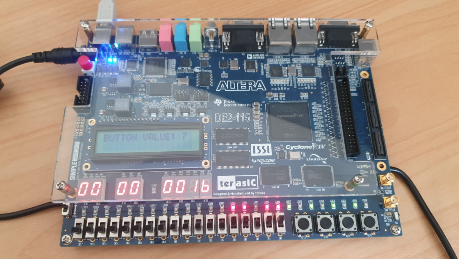
The example_lcd_led_switches_buttons directory of the lab’s resource package illustrates an example of programming the Nios II to interact with peripherals on the DE2 115 board.
You can copy the entire contents of the example_lcd_led_switches_buttons directory to your hello_lab project directory (e.g c:\compsys723\lab\software\hello_lab). After copying the files into your project directory, right-click the project in the Project Explorer in the Nios II IDE and select “ Refresh”. Rebuild the project and run it on the Nios II processor.
Refer to previous sections for instructions on building and running a Nios II application.
TIP
The value 7 on the display comes from the push button base
# example_lcd_led_switches_buttons
#include <system.h>
#include <altera_avalon_pio_regs.h>
#include <stdio.h>
int main()
{
  // declare the working variables
  unsigned int uiSwitchValue = 0;
  unsigned int uiButtonsValue = 0;
  unsigned int uiButtonsValuePrevious = 0;
  // the pointer to the lcd
  FILE *lcd;
  // print the information to the stdout
  printf("Hello from Nios II!\n");
  // set the value to the green leds
  IOWR_ALTERA_AVALON_PIO_DATA(GREEN_LEDS_BASE, 0xaa); // 0xaa = 0b10101010
  // open the character LCD
  lcd = fopen(CHARACTER_LCD_NAME, "w");
  // the program loop
  while(1)
  {
    // read the value of the switch and store to uiSwitchValue
    uiSwitchValue = IORD_ALTERA_AVALON_PIO_DATA(SLIDE_SWITCH_BASE);
    // write the value of the switches to the red LEDs
    IOWR_ALTERA_AVALON_PIO_DATA(RED_LEDS_BASE, uiSwitchValue);
    // also write the value of the switches to the seven segments display
    IOWR_ALTERA_AVALON_PIO_DATA(SEVEN_SEG_BASE, uiSwitchValue);
    // store the previous pressed buttons
    uiButtonsValuePrevious = uiButtonsValue;
    // read the current pressed buttons
    uiButtonsValue = IORD_ALTERA_AVALON_PIO_DATA(PUSH_BUTTON_BASE);
    // if the lcd is open successfully
    if(lcd != NULL)
    {
      if(uiButtonsValuePrevious != uiButtonsValue)
      {
        // print the value of the buttons in the character lcd
        #define ESC 27
        #define CLEAR_LCD_STRING "[2J"
        fprintf(lcd, "%c%s", ESC, CLEAR_LCD_STRING);
        fprintf(lcd, "BUTTON VALUE: %d\n", uiButtonsValue);
      }
    }
  }
  // close the lcd
  fclose(lcd);
  return 0;
}
2
3
4
5
6
7
8
9
10
11
12
13
14
15
16
17
18
19
20
21
22
23
24
25
26
27
28
29
30
31
32
33
34
35
36
37
38
39
40
41
42
43
44
45
46
47
# Writing an interrupt service routine (ISR)
The interrupt service routine (ISR) is a specialized function that is associated with an IRQ of a corresponding hardware component. The registered ISR will be activated or called when the interrupt occurs.
IRQ - Interrupt Request
The IRQ (Interrupt Request) of a hardware component is a unique number assigned to it by the system BIOS or operating system. The IRQ is used to communicate with the CPU and other system components to notify them of events or requests that require attention from the hardware device.
Each hardware component in a computer system, such as the keyboard, mouse, sound card, network adapter, etc., is assigned a specific IRQ by the system. This allows the CPU to efficiently manage the flow of data and instructions between the hardware components and the operating system.
In modern computer systems, IRQs are typically managed automatically by the operating system using a technique called Plug and Play (PnP). However, in some cases, users may need to manually configure IRQ settings, especially in older systems or when using legacy hardware components.
To implement an ISR, these requirements must be met:
The hardware peripheral in question must be capable of generating an interrupt. Output-only peripherals usually do not meet this criterion. An IRQ number is assigned (not 1) to each peripheral in
system.hwhich can generate interrupts.You have to register the ISR with the associated interrupt. This configures the ISR to run when the interrupt is triggered.
Within the ISR, you may need to do some housekeeping work such as clearing the flags which caused the interrupt, or reenabling the interrupt if required (sometimes the interrupt is disabled once the ISR is entered).
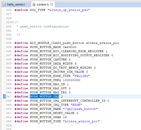
Looking at the definitions for PUSH_BUTTON in system.h, we can see that PUSH_BUTTON_IRQ is defined . We are also going to use PUSH_BUTTON_BASE instead of hard coding the address of the buttons.

# PIO and ISR relevant functions
IORD_ALTERA_AVALON_PIO_IRQ_MASK(BASE_ADDR): This will return an “interrupt mask” value that indicates which input ports of a component have interrupts enabled. For instance, when interrupts are enabled for the first 3 buttons, a value of 7 ( 111 in binary, which “masks” the first 3 bits) will be returned.
IOWR_ALTERA_AVALON_PIO_IRQ_MASK(BASE_ADDR, value): This function is used to set the interrupt mask which is explained above.
IORD_ALTERA_AVALON_PIO_EDGE_CAP(BASE_ADDR): This function returns the value of the edge capture register of a PIO peripheral.
During system generation, a PIO core can be configured to capture different types of edges, such as low-to-high transitions and high-to-low transitions. When an edge from an input port is captured, the corresponding bit is set in the edge capture peripheral. In the system provided in this lab, the buttons PIO peripheral has been configured to trigger an interrupt when any of the bits in the edge capture register have been set. The value returned by this function can be read inside an ISR to determine which input port (a button in this case) caused the interrupt.
IOWR_ALTERA_AVALON_PIO_EDGE_CAP(BASE_ADDR, value): This function writes a value to the edge capture register which was explained above.
# Register the PIO ISR
The ISR implementation has to have a function prototype of this form:
void name_of_the_isr_function (void* context, alt_u32 id)
The first argument is a void pointer. This means that you can pass any kind of pointer to the ISR function.
The second argument is the id of the interrupt, this is the IRQ number which the ISR is associated with. For the buttons peripheral, it is PUSH_BUTTONS_IRQ as mentioned previously. Both the context pointer and the interrupt id must be passed to the ISR register function as well.
The ISR registering function has the following signature:
int alt_irq_register ( alt_u32 id, void* context, void (*isr)(void* , alt_u32))
The first argument is the IRQ number of the interrupt.
The second argument is a pointer to anything which the programmer may wish to pass to the interrupt (if you are working with global variables, then you can just pass NULL to it).
The third argument is a function pointer, which points to the ISR function. To use these functions you need to include sys/alt_irq.h
The code example_button_isr shows an example of a button ISR which changes the value of the context
passed to it. The value which is stored, indicates which button has been pressed. This value is then output to the green LEDs.
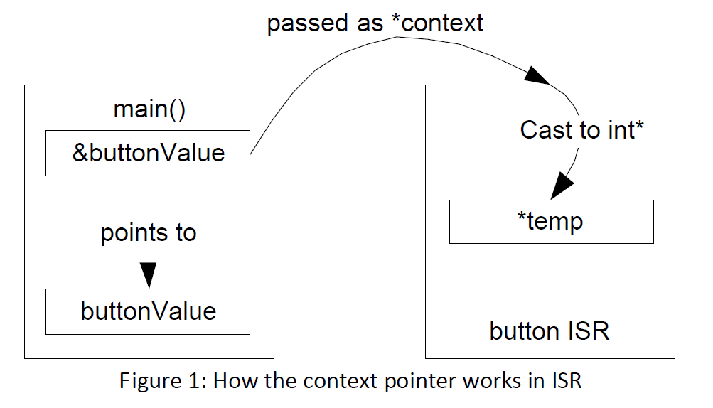
Figure 1 illustrates how the buttonValue variable is changed by the ISR. In the main function, the address of buttonValue (obtained using &buttonValue) is passed as the context to the button ISR when registering the ISR in line 27.
When an interrupt is triggered, the context is passed to the button ISR, where it is cast back to an integer pointer (*temp). As a result, the ISR can modify the value of the buttonValue variable using the temp pointer.
#include "system.h"                     // to use the symbolic names
#include "altera_avalon_pio_regs.h" 	// to use PIO functions
#include "alt_types.h"                 	// alt_u32 is a kind of alt_types
#include "sys/alt_irq.h"              	// to register interrupts
// first we write our interrupt function
void button_interrupts_function(void* context, alt_u32 id)
{
  // need to cast the context first before using it
  int* temp = (int*) context;
  (*temp) = IORD_ALTERA_AVALON_PIO_EDGE_CAP(PUSH_BUTTON_BASE);

  // clears the edge capture register
  IOWR_ALTERA_AVALON_PIO_EDGE_CAP(PUSH_BUTTON_BASE, 0x7);
}

int main(void)
{
  int buttonValue = 0;

  // clears the edge capture register. Writing 1 to bit clears pending interrupt for corresponding button.
  IOWR_ALTERA_AVALON_PIO_EDGE_CAP(PUSH_BUTTON_BASE, 0x7);

  // enable interrupts for all buttons
  IOWR_ALTERA_AVALON_PIO_IRQ_MASK(PUSH_BUTTON_BASE, 0x7);

  // register the ISR
  alt_irq_register(PUSH_BUTTON_IRQ,(void*)&buttonValue, button_interrupts_function);

  // need this to keep the program alive
  while(1)
  {
    IOWR_ALTERA_AVALON_PIO_DATA(GREEN_LEDS_BASE, buttonValue);
  }
  return 0;
}
2
3
4
5
6
7
8
9
10
11
12
13
14
15
16
17
18
19
20
21
22
23
24
25
26
27
28
29
30
31
32
33
34
35
This code is an example of how to set up interrupt-driven input from push buttons and output to green LEDs on an Altera FPGA using the NIOS II processor.
The main function initializes a variable buttonValue to 0 and then clears the edge capture register for the push button base address. It then enables interrupts for all three push buttons by setting the interrupt mask bits for the push button base address.
The code then registers the interrupt service routine (button_interrupts_function) using the alt_irq_register function. This function takes three parameters: the interrupt ID (in this case PUSH_BUTTON_IRQ), a pointer to a context variable (&buttonValue), and the name of the ISR (button_interrupts_function).
The button_interrupts_function is the actual interrupt service routine. It first casts the context variable from void* to an int* so that it can access the value of buttonValue. It then reads the value of the edge capture register for the push button base address and stores it in buttonValue. Finally, it clears the edge capture register by writing 0x7 to it.
After registering the ISR, the main function enters an infinite loop that continuously writes the value of buttonValue to the green LED base address.
Overall, this code sets up interrupt-driven input from push buttons and output to green LEDs. When a push button is pressed, the corresponding LED will light up.
# Using Timer ISRs
A timer ISR is a bit different to the PIO ISRs. A timer ISR must have a function prototype of this form:
alt_u32 timer_isr_function(void* context)
The return value of the timer ISR is the timeout value of the next timer iteration (which will be described in further detail below). If it is 0 then the timer is stopped once control returns from the timer ISR function.
The timer ISR does not need to be registered like a general ISR. Instead, the timer must be started using the following function:
int alt_alarm_start(alt_alarm* timer_pointer, alt_u32 time_to_run,
                    alt_u32 (*function_pointer_to_the_timer_isr) (void* context),
                    void* context);
2
3
The first argument is a pointer to an alt_alarm structure which is used by the HAL to manage the timer.
The second argument is the time period after which the first timeout is generated.
The third argument is a function pointer to the ISR function for the timer.
The last argument is the context pointer that is passed to the timer ISR. The function will return a negative value if the timer fails to start. To use these functions, you need to include sys/alt_alarm.h
# Timer ISR example
FreeRTOS is a popular real-time operating system (RTOS) that provides a range of features for embedded systems, including support for timer interrupts. Here is an example of a timer ISR implementation for the DE2-115 board using FreeRTOS:
#include "FreeRTOS.h"
#include "task.h"
#include "altera_avalon_timer_regs.h"
#include "sys/alt_irq.h"

#define TIMER_INTERRUPT_PERIOD 1000 // 1ms

static void timer_isr(void* context) {
    // Clear the timer interrupt flag
    IOWR_ALTERA_AVALON_TIMER_STATUS(TIMER_BASE, 0);

    // Do something in response to the timer interrupt
    // For example, signal a task to run
    xTaskResumeAll();
}

int main() {
    // Initialize the timer
    IOWR_ALTERA_AVALON_TIMER_CONTROL(TIMER_BASE, ALTERA_AVALON_TIMER_CONTROL_STOP_MSK);
    IOWR_ALTERA_AVALON_TIMER_CONTROL(TIMER_BASE, ALTERA_AVALON_TIMER_CONTROL_CONT_MSK | ALTERA_AVALON_TIMER_CONTROL_ITO_MSK);
    IOWR_ALTERA_AVALON_TIMER_PERIODL(TIMER_BASE, TIMER_INTERRUPT_PERIOD & 0xFFFF);
    IOWR_ALTERA_AVALON_TIMER_PERIODH(TIMER_BASE, (TIMER_INTERRUPT_PERIOD >> 16) & 0xFFFF);

    // Register the timer ISR
    alt_ic_isr_register(TIMER_IRQ_INTERRUPT_CONTROLLER_ID, TIMER_IRQ, timer_isr, NULL, 0);

    // Start the FreeRTOS scheduler
    vTaskStartScheduler();

    return 0;
}
2
3
4
5
6
7
8
9
10
11
12
13
14
15
16
17
18
19
20
21
22
23
24
25
26
27
28
29
30
31
32
In this example, we first define a constant TIMER_INTERRUPT_PERIOD that specifies the period of the timer interrupt in milliseconds. We then define the timer ISR function timer_isr, which simply clears the timer interrupt flag and resumes all tasks using the xTaskResumeAll function.
In the main function, we first initialize the timer with the desired period using the IOWR_ALTERA_AVALON_TIMER_* functions. We then register the timer ISR using the alt_ic_isr_register function from the Altera HAL library. Finally, we start the FreeRTOS scheduler using the vTaskStartScheduler function.
Note that this is just a simple example and that in practice, you would typically use the timer ISR to perform more complex operations, such as triggering a task to run or updating the state of the system based on the elapsed time.
# Using a PS/2 peripheral
The PS/2 peripheral is an Avalon Slave which communicates with PS/2 devices such as a keybo
ard. The peripheral can be used in application code by either polling or by using an interrupt. Software routines are provided for using a keyboard that is connected to the PS/2 port. In order to use these routines, you need to include the altera_avalon_ps2.h and altera_up_ps2_keyboard.h header files. An example of using a PS/2 keyboard as an input device can be found in the example_ps2 folder of the lab’s resource package.
In the previous example, the read_make_code function which decoded the key event and key code, blocks the main loop of the program. To avoid this, we can use an interrupt service routine as seen in the example_ps2_irq example.
# example_ps2
// Part of the file provided by Terasic
#include <stdio.h>
#include "system.h"
#include "io.h"
#include "altera_up_avalon_ps2.h"
#include "altera_up_ps2_keyboard.h"
int main()
{
  alt_up_ps2_dev * ps2_device = alt_up_ps2_open_dev(PS2_NAME);

  if(ps2_device == NULL){
    printf("can't find PS/2 device\n");
    return 1;
  }

  alt_up_ps2_clear_fifo (ps2_device) ;

  char ascii;
  int status = 0;
  unsigned char key = 0;
  KB_CODE_TYPE decode_mode;
  while(1)
  {
      // blocking function call
      status = decode_scancode (ps2_device, &decode_mode , &key , &ascii) ;
      if ( status == 0 ) //success
      {
        // print out the result
        switch ( decode_mode )
        {
          case KB_ASCII_MAKE_CODE :
            printf ( "ASCII   : %x\n", key ) ;
            break ;
          case KB_LONG_BINARY_MAKE_CODE :
            // do nothing
          case KB_BINARY_MAKE_CODE :
            printf ( "MAKE CODE : %x\n", key ) ;
            break ;
          case KB_BREAK_CODE :
            // do nothing
          default :
            printf ( "DEFAULT   : %x\n", key ) ;
            break ;
        }
        IOWR(SEVEN_SEG_BASE,0 ,key);
      }

  }
  return 0;
}
2
3
4
5
6
7
8
9
10
11
12
13
14
15
16
17
18
19
20
21
22
23
24
25
26
27
28
29
30
31
32
33
34
35
36
37
38
39
40
41
42
43
44
45
46
47
48
49
50
# example_ps2_irq
#include <stdio.h>
#include "system.h"
#include "io.h"
#include "altera_up_avalon_ps2.h"
#include "altera_up_ps2_keyboard.h"
#include "sys/alt_irq.h"

void ps2_isr (void* context, alt_u32 id)
{
  char ascii;
  int status = 0;
  unsigned char key = 0;
  KB_CODE_TYPE decode_mode;
  status = decode_scancode (context, &decode_mode , &key , &ascii) ;
  if ( status == 0 ) //success
  {
    // print out the result
    switch ( decode_mode )
    {
      case KB_ASCII_MAKE_CODE :
        printf ( "ASCII   : %x\n", key ) ;
        break ;
      case KB_LONG_BINARY_MAKE_CODE :
        // do nothing
      case KB_BINARY_MAKE_CODE :
        printf ( "MAKE CODE : %x\n", key ) ;
        break ;
      case KB_BREAK_CODE :
        // do nothing
      default :
        printf ( "DEFAULT   : %x\n", key ) ;
        break ;
    }
    IOWR(SEVEN_SEG_BASE,0 ,key);
  }
}
int main()
{
  alt_up_ps2_dev * ps2_device = alt_up_ps2_open_dev(PS2_NAME);

  if(ps2_device == NULL){
    printf("can't find PS/2 device\n");
    return 1;
  }

  alt_up_ps2_clear_fifo (ps2_device) ;

  alt_irq_register(PS2_IRQ, ps2_device, ps2_isr);
  // register the PS/2 interrupt
  IOWR_8DIRECT(PS2_BASE,4,1);
  while(1){}
  return 0;
}
2
3
4
5
6
7
8
9
10
11
12
13
14
15
16
17
18
19
20
21
22
23
24
25
26
27
28
29
30
31
32
33
34
35
36
37
38
39
40
41
42
43
44
45
46
47
48
49
50
51
52
53
What is the difference? Which is better?
The first code (example_ps2) is a simple program that continuously polls for keyboard input using a while loop, polling from a PS/2 keyboard interface. It waits for a key press, decodes the key code, and prints it to the console. It also displays the scan-code on a 7-segment display.
The second code (example_ps2_irq) is an interrupt-driven implementation of the same PS/2 keyboard interface. Instead of polling the interface, the program registers an interrupt service routine (ISR) to be called whenever there is a PS/2 event. The ISR decodes the scan-code, prints the result on the console and displays the scan-code on a 7-segment display.
The advantage of the interrupt-driven implementation is that it does not require constant polling of the interface, which reduces the CPU load. Instead, the ISR is only called when there is a PS/2 event, which frees up the CPU to do other tasks. The disadvantage is that it requires more code to set up the interrupt and the ISR, which can be more complicated than a simple polling implementation.
The interrupt-based approach is generally considered better for handling real-time events like keyboard input. It allows the program to immediately respond to input as it is received, rather than having to wait for the next polling interval. The interrupt approach can be more efficient in terms of CPU utilization since it doesn't require the program to continuously check for input.
Therefore, the second code is generally considered better for handling keyboard input from a PS/2 device, especially in real-time applications.
# Using the VGA display controller
You can find example codes (char_buffer.c and pixel_buffer.c) on the us e of VGA controller in Additional example codes.
Go through the example code for clues as to how you might display information on the screen.
# char_buffer.c
#include <stdio.h>
#include <unistd.h>
#include "system.h"
#include "altera_up_avalon_video_character_buffer_with_dma.h"
#include "altera_up_avalon_video_pixel_buffer_dma.h"

int main()
{
	//reset the display
	alt_up_pixel_buffer_dma_dev *pixel_buf;
	pixel_buf = alt_up_pixel_buffer_dma_open_dev(VIDEO_PIXEL_BUFFER_DMA_NAME);
	if(pixel_buf == NULL){
		printf("Cannot find pixel buffer device\n");
	}
	alt_up_pixel_buffer_dma_clear_screen(pixel_buf, 0);

	//initialize character buffer
	alt_up_char_buffer_dev *char_buf;
	char_buf = alt_up_char_buffer_open_dev("/dev/video_character_buffer_with_dma");
	if(char_buf == NULL){
		printf("can't find char buffer device\n");
	}

	while(1){
		alt_up_char_buffer_string(char_buf, "Hello World", 40, 30);
		usleep(1000000);
		alt_up_char_buffer_draw(char_buf, '!', 51, 30);
		usleep(1000000);
		alt_up_char_buffer_clear(char_buf);
		usleep(1000000);
	}

  return 0;
}
2
3
4
5
6
7
8
9
10
11
12
13
14
15
16
17
18
19
20
21
22
23
24
25
26
27
28
29
30
31
32
33
34
35
# char_buffer.c
#include <stdio.h>
#include <unistd.h>
#include "system.h"
#include "altera_avalon_pio_regs.h"
#include "altera_up_avalon_video_pixel_buffer_dma.h"
int main()
{
	alt_up_pixel_buffer_dma_dev *pixel_buf;
	pixel_buf = alt_up_pixel_buffer_dma_open_dev(VIDEO_PIXEL_BUFFER_DMA_NAME);
	if(pixel_buf == NULL){
		printf("Cannot find pixel buffer device\n");
	}

	alt_up_pixel_buffer_dma_clear_screen(pixel_buf, 0);
	alt_up_pixel_buffer_dma_draw_box(pixel_buf, 100, 100, 200, 200, 0x3ff, 0); //Green
	alt_up_pixel_buffer_dma_draw_rectangle(pixel_buf, 250, 300, 400, 400, 0x3ff << 10, 0); //Red
	alt_up_pixel_buffer_dma_draw_line(pixel_buf, 500, 150, 600, 350, 0x3ff << 20, 0); //Blue
	alt_up_pixel_buffer_dma_draw_hline(pixel_buf, 300, 400, 150, ((0x3ff << 20) + (0x3ff << 10) + (0x3ff)), 0); //White
	alt_up_pixel_buffer_dma_draw_vline(pixel_buf, 50, 50, 400, ((0x3ff << 20) + (0x3ff)), 0); //Cyan

	while(1){
	}

	return 0;
}
2
3
4
5
6
7
8
9
10
11
12
13
14
15
16
17
18
19
20
21
22
23
24
25
The first code is an example of using the character buffer in a display, while the second code is an example of drawing various shapes on a pixel buffer.
The character buffer is a type of memory that is used to display text characters in a fixed-size grid, and it is useful for displaying text-based user interfaces. The first code initializes a character buffer and displays the string "Hello World" in the center of the screen, then draws an exclamation mark and clears the buffer repeatedly.
On the other hand, the pixel buffer is a type of memory that is used to display images, and it is useful for displaying graphics-based user interfaces. The second code initializes a pixel buffer and draws various shapes on it, such as a green box, a red rectangle, a blue line, a white horizontal line, and a cyan vertical line.
Which code is better depends on what you want to achieve. If you want to display text-based information, the first code using the character buffer would be more appropriate. If you want to display graphics-based information, the second code using the pixel buffer would be more appropriate.
# Using the Frequency analyser
You can find details about this component in the assignment hand out and example codes in Additional example codes
# freq_analyser
#include <stdio.h>
#include <unistd.h>
#include "system.h"
#include "sys/alt_irq.h"
#include "io.h"
#include "altera_avalon_pio_regs.h"
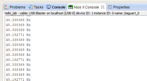
void freq_relay(){
unsigned int temp = IORD(FREQUENCY_ANALYSER_BASE, 0);
printf("%f Hz\n", 16000/(double)temp);
return;
}
int main()
{
alt_irq_register(FREQUENCY_ANALYSER_IRQ, 0, freq_relay);
while(1){
IOWR_ALTERA_AVALON_PIO_DATA(GREEN_LEDS_BASE, 0x55);
usleep(1000000);
IOWR_ALTERA_AVALON_PIO_DATA(GREEN_LEDS_BASE, 0xaa);
usleep(1000000);
}
return 0;
}
2
3
4
5
6
7
8
9
10
11
12
13
14
15
16
17
18
19
20
21
22
23
24
25
26
27
This code reads a frequency signal from a frequency analyzer module and prints the frequency in Hz on the console. It also blinks the green LEDs on the board in a pattern.
The function freq_relay reads the frequency signal from the frequency analyzer module using the IORD function and calculates the frequency in Hz using a formula. The frequency value is printed on the console using printf.
The alt_irq_register function is used to register an interrupt handler function freq_relay for the frequency analyzer interrupt. This means that the function freq_relay will be called every time the frequency analyzer module generates an interrupt.
`IORD` function
The IORD function is a pre-defined function in the Altera HAL (Hardware Abstraction Layer) library that is used to read the current value of a specified register in the system. The function takes two parameters: the base address of the device, and the offset value of the register within that device. The function returns the current value of the specified register.
In the provided code, IORD(FREQUENCY_ANALYSER_BASE, 0) is used to read the value of the register at offset 0 within the device at the base address FREQUENCY_ANALYSER_BASE. This value is then used to calculate and print the frequency of an input signal.
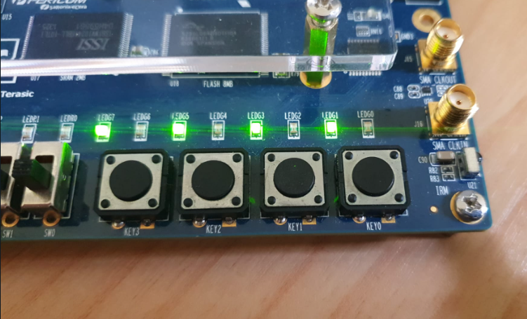
In the main function, the green LEDs are turned on and off in alternating patterns using the IOWR_ALTERA_AVALON_PIO_DATA function and usleep is used to delay between each pattern.
The main function does not exit, so the program continues to run indefinitely until it is manually stopped.
# Part 3 - Intro to FreeRTOS
In this section we will introduce you to FreeRTOS, the operating system that will be used as the basis for your assignment. We will explore the use of FreeRTOS on the Nios II processor. A real time operating system (RTOS) can be utilized to run software with multiple tasks or threads on the provided single processor hardware platform.
Important Resources:
- FreeRTOS main page
- API Reference
- Your lecture slides
- FreeRTOS code (provided on Canvas)
# Create a simple software application with FreeRTOS
In order to use FreeRTOS in our application, we need to include a number of essential files.
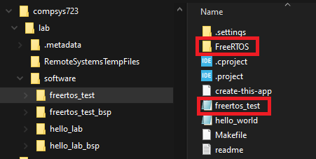
Create a new Nios II application project (called freertos_test ) in addition to an associated BSP (called freertos_test_bsp). Make sure you remove any C files that may be generated for you in the application project directory to prevent errors due to an existing definition of a main function.
Copy the freertos directory from the lab’s resource package to the folder of the application software, for instance C:\compsys723\lab\software\freertos _test. Also copy the example application’s source code freertos_test.c from the freertos_test directory in the resource package) to the project directory as shown in Figure 2.
In order for the provided FreeRTOS files to work, you may need to modify the system.h file in the BSP project (freertos_test_bsp).
Make sure the following entry is present:
#define ALT_LEGACY_INTERRUPT_API_PRESENT
(as opposed to ALT_ENHANCED_INTERRUPT_API_PRESENT)
2
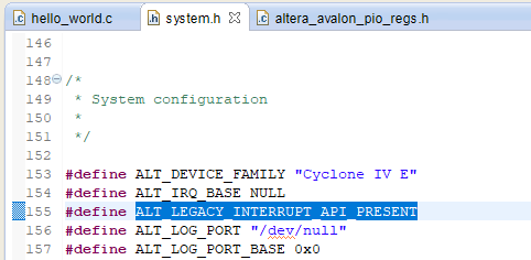
The system.h file is re generated whenever the BSP settings are modified. As a result, this change must be re applied any time the BSP settings are updated.
In this example, two tasks are created with the same priority. Each task prints out an identifier string (e.g.Task 1 or Task 2), and waits for 1 second by calling the vTaskDelay function.
To run the example, return to the IDE to refresh and build the freertos_test project. Run the project using the procedure described in the previous section.
/* Standard includes. */
#include <stddef.h>
#include <stdio.h>
#include <string.h>

/* Scheduler includes. */
#include "freertos/FreeRTOS.h"
#include "freertos/task.h"
#include "freertos/queue.h"

/* The parameters passed to the reg test tasks.  This is just done to check
 the parameter passing mechanism is working correctly. */
#define mainREG_TEST_1_PARAMETER    ( ( void * ) 0x12345678 )
#define mainREG_TEST_2_PARAMETER    ( ( void * ) 0x87654321 )
#define mainREG_TEST_PRIORITY       ( tskIDLE_PRIORITY + 1)
static void prvFirstRegTestTask(void *pvParameters);
static void prvSecondRegTestTask(void *pvParameters);

/*
 * Create the demo tasks then start the scheduler.
 */
int main(void)
{
	/* The RegTest tasks as described at the top of this file. */
	xTaskCreate( prvFirstRegTestTask, "Rreg1", configMINIMAL_STACK_SIZE, mainREG_TEST_1_PARAMETER, mainREG_TEST_PRIORITY, NULL);
	xTaskCreate( prvSecondRegTestTask, "Rreg2", configMINIMAL_STACK_SIZE, mainREG_TEST_2_PARAMETER, mainREG_TEST_PRIORITY, NULL);

	/* Finally start the scheduler. */
	vTaskStartScheduler();

	/* Will only reach here if there is insufficient heap available to start
	 the scheduler. */
	for (;;);
}
static void prvFirstRegTestTask(void *pvParameters)
{
	while (1)
	{
		printf("Task 1\n");
		vTaskDelay(1000);
	}

}
static void prvSecondRegTestTask(void *pvParameters)
{
	while (1)
	{
		printf("Task 2\n");
		vTaskDelay(1000);
	}
}
2
3
4
5
6
7
8
9
10
11
12
13
14
15
16
17
18
19
20
21
22
23
24
25
26
27
28
29
30
31
32
33
34
35
36
37
38
39
40
41
42
43
44
45
46
47
48
49
50
51
What do you see? Why?
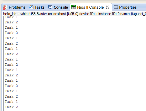
This is a simple C program that demonstrates the use of FreeRTOS to create and run two tasks that print messages to the console every second. The program consists of two tasks: prvFirstRegTestTask and prvSecondRegTestTask.
The main function creates two instances of these tasks by calling xTaskCreate, passing in a task function pointer, a task name, a stack size, a parameter to be passed to the task function, a task priority, and a handle to the created task (which is not used in this program).
The prvFirstRegTestTask and prvSecondRegTestTask functions are very similar. They are both infinite loops that print a message to the console using printf and then delay for one second using vTaskDelay.
Finally, the vTaskStartScheduler function is called to start the FreeRTOS scheduler, which will run the two tasks in parallel.
If there is insufficient heap available to start the scheduler, the program will enter an infinite loop.
TIP
For some reason, these 2 lines on the portable.h file had to be commented. lines 163 and 166.
//void *pvPortMalloc( size_t xSize ) PRIVILEGED_FUNCTION;
void vPortFree( void *pv ) PRIVILEGED_FUNCTION;
void vPortInitialiseBlocks( void ) PRIVILEGED_FUNCTION;
//size_t xPortGetFreeHeapSize( void ) PRIVILEGED_FUNCTION;
size_t xPortGetMinimumEverFreeHeapSize( void ) PRIVILEGED_FUNCTION;
2
3
4
5
here is the erros in case its not commented:
22:00:48 **** Incremental Build of configuration Nios II for project freertos_test ****
make all
Info: Building ../freertos_test_bsp/
C:/intelFPGA_lite/17.0/nios2eds/bin/gnu/H-x86_64-mingw32/bin/make --no-print-directory -C ../freertos_test_bsp/
[BSP build complete]
Info: Compiling freertos/croutine.c to obj/default/freertos/croutine.o
nios2-elf-gcc -xc -MP -MMD -c -I../freertos_test_bsp//HAL/inc -I../freertos_test_bsp/ -I../freertos_test_bsp//drivers/inc  -pipe -D__hal__ -DALT_NO_INSTRUCTION_EMULATION -DALT_SINGLE_THREADED    -O0 -g -Wall   -mhw-div -mhw-mul -mno-hw-mulx -mgpopt=global  -o obj/default/freertos/croutine.o freertos/croutine.c
Info: Compiling freertos/event_groups.c to obj/default/freertos/event_groups.o
nios2-elf-gcc -xc -MP -MMD -c -I../freertos_test_bsp//HAL/inc -I../freertos_test_bsp/ -I../freertos_test_bsp//drivers/inc  -pipe -D__hal__ -DALT_NO_INSTRUCTION_EMULATION -DALT_SINGLE_THREADED    -O0 -g -Wall   -mhw-div -mhw-mul -mno-hw-mulx -mgpopt=global  -o obj/default/freertos/event_groups.o freertos/event_groups.c
Info: Compiling freertos/heap.c to obj/default/freertos/heap.o
nios2-elf-gcc -xc -MP -MMD -c -I../freertos_test_bsp//HAL/inc -I../freertos_test_bsp/ -I../freertos_test_bsp//drivers/inc  -pipe -D__hal__ -DALT_NO_INSTRUCTION_EMULATION -DALT_SINGLE_THREADED    -O0 -g -Wall   -mhw-div -mhw-mul -mno-hw-mulx -mgpopt=global  -o obj/default/freertos/heap.o freertos/heap.c
freertos/heap.c:147:7: error: conflicting types for 'pvPortMalloc'
 void *pvPortMalloc( size_t xWantedSize )
       ^
In file included from freertos/FreeRTOS.h:104:0,
                 from freertos/heap.c:82:
freertos/portable.h:163:7: note: previous declaration of 'pvPortMalloc' was here
 void *pvPortMalloc( size_t xSize ) PRIVILEGED_FUNCTION;
       ^
freertos/heap.c:262:8: error: conflicting types for 'xPortGetFreeHeapSize'
 size_t xPortGetFreeHeapSize( void )
        ^
In file included from freertos/FreeRTOS.h:104:0,
                 from freertos/heap.c:82:
freertos/portable.h:166:8: note: previous declaration of 'xPortGetFreeHeapSize' was here
 size_t xPortGetFreeHeapSize( void ) PRIVILEGED_FUNCTION;
        ^
make: *** [obj/default/freertos/heap.o] Error 1

22:01:02 Build Finished (took 14s.432ms)
2
3
4
5
6
7
8
9
10
11
12
13
14
15
16
17
18
19
20
21
22
23
24
25
26
27
28
29
30
# Look into more details, communication and synchronization between threads
You may now proceed to the next example:
freertos_semaphore , which can also be found in the lab resource package. Replace freertos_test.cwith freertos_semaphore.c.
Tasks of a FreeRTOS application have the following signature:
void task_function_name(void *pvParameters)
{

}
2
3
4
A task function usually contains an infinite loop. Within this loop there can be one or more RTOS API calls, such as time delay functions or functions which acquire semaphores. The task may release processor control explicitly using these mechanisms or it may be pre-empted by a task with a higher priority.
Each task has its own stack with a stack size that is specified when creating the task. In this example, the TASK_STACKSIZE constant is used to define the size of the stack of each task . Semaphores and queues are represented using the xSemaphoreHandle and xQueueHandle types. They are usually declared globally, for instance, shared_resource_sem in this example is a global semaphore which can be used by any task.
# freertos_semaphore.c
// Standard includes
#include <stddef.h>
#include <stdio.h>
#include <string.h>

// Scheduler includes
#include "freertos/FreeRTOS.h"
#include "freertos/task.h"
#include "freertos/queue.h"
#include "freertos/semphr.h"

#include <altera_avalon_pio_regs.h>

// Definition of Task Stacks
#define   TASK_STACKSIZE       2048

// Definition of Task Priorities
#define PRINT_STATUS_TASK_PRIORITY 14
#define GETSEM_TASK1_PRIORITY      13
#define GETSEM_TASK2_PRIORITY      12
#define RECEIVE_TASK1_PRIORITY    11
#define RECEIVE_TASK2_PRIORITY    10
#define SEND_TASK_PRIORITY        9

// Definition of Message Queue
#define   MSG_QUEUE_SIZE  30
QueueHandle_t msgqueue;

// used to delete a task
TaskHandle_t xHandle;

// Definition of Semaphore
SemaphoreHandle_t shared_resource_sem;

// globals variables
unsigned int number_of_messages_sent = 0;
unsigned int number_of_messages_received_task1 = 0;
unsigned int number_of_messages_received_task2 = 0;
unsigned int getsem_task1_got_sem = 0;
unsigned int getsem_task2_got_sem = 0;
char sem_owner_task_name[20];

// Local Function Prototypes
int initOSDataStructs(void);
int initCreateTasks(void);

// The following test prints out status information every 3 seconds.
void print_status_task(void *pvParameters)
{
	while (1)
	{
		vTaskDelay(3000);
		printf("****************************************************************\n");
		printf("Hello From FreeRTOS Running on NIOS II.  Here is the status:\n");
		printf("\n");
		printf("The number of messages sent by the send_task:         %d\n", number_of_messages_sent);
		printf("\n");
		printf("The number of messages received by the receive_task1: %d\n", number_of_messages_received_task1);
		printf("\n");
		printf("The number of messages received by the receive_task2: %d\n", number_of_messages_received_task2);
		printf("\n");
		printf("The shared resource is owned by: %s\n", &sem_owner_task_name[0]);
		printf("\n");
		printf("The Number of times getsem_task1 acquired the semaphore %d\n", getsem_task1_got_sem);
		printf("\n");
		printf("The Number of times getsem_task2 acquired the semaphore %d\n", getsem_task2_got_sem);
		printf("\n");
		printf("****************************************************************\n");
		printf("\n");
	}
}

// The next two task compete for a shared resource via a semaphore.  The name of
// the task that owns the semaphore is copied into the global variable
// sem_owner_task_name[].
void getsem_task1(void *pvParameters)
{
	while (1)
	{
		xSemaphoreTake(shared_resource_sem, portMAX_DELAY);
		// block forever until receive the mutex
		strcpy(&sem_owner_task_name[0], "getsem_task1");
		getsem_task1_got_sem++;
		xSemaphoreGive(shared_resource_sem);
		vTaskDelay(100);
	}
}

void getsem_task2(void *pvParameters)
{
	while (1)
	{
		xSemaphoreTake(shared_resource_sem, portMAX_DELAY);
		// block forever until receive the mutex
		strcpy(&sem_owner_task_name[0], "getsem_task2");
		getsem_task2_got_sem++;
		xSemaphoreGive(shared_resource_sem);
		vTaskDelay(130);
	}
}

// The following task fills up a message queue with incrementing data.  The data
// is not actually used by the application.  If the queue is full the task is
// suspended for 1 second.
void send_task(void *pvParameters)
{
	unsigned int msg = 0;
	while (1)
	{
		if (xQueueSend(msgqueue, (void *)&msg, 0) == pdPASS)
		{
			// in the message queue
			msg++;
			number_of_messages_sent++;
		}
		else
		{
			vTaskDelay(1000);
		}
	}
}

// The next two task pull messages in the queue at different rates.  The number
// of messages received by the task is incremented when a new message is received
void receive_task1(void *pvParameters)
{
	unsigned int *msg;
	while (1)
	{
		xQueueReceive(msgqueue, &msg, portMAX_DELAY);
		number_of_messages_received_task1++;
		vTaskDelay(333);
	}
}

void receive_task2(void *pvParameters)
{
	unsigned int *msg;
	while (1)
	{
		xQueueReceive(msgqueue, &msg, portMAX_DELAY);
		number_of_messages_received_task2++;
		vTaskDelay(1000);
	}
}

int main(int argc, char* argv[], char* envp[])
{
	initOSDataStructs();
	initCreateTasks();
	vTaskStartScheduler();
	for (;;);
	return 0;
}

// This function simply creates a message queue and a semaphore
int initOSDataStructs(void)
{
	msgqueue = xQueueCreate( MSG_QUEUE_SIZE, sizeof( void* ) );
	shared_resource_sem = xSemaphoreCreateCounting( 9999, 1 );
	return 0;
}

// This function creates the tasks used in this example
int initCreateTasks(void)
{
	xTaskCreate(getsem_task1, "getsem_task1", TASK_STACKSIZE, NULL, GETSEM_TASK1_PRIORITY, NULL);
	xTaskCreate(getsem_task2, "getsem_task2", TASK_STACKSIZE, NULL, GETSEM_TASK2_PRIORITY, NULL);
	xTaskCreate(receive_task1, "receive_task1", TASK_STACKSIZE, NULL, RECEIVE_TASK1_PRIORITY, NULL);
	xTaskCreate(receive_task2, "receive_task2", TASK_STACKSIZE, NULL, RECEIVE_TASK2_PRIORITY, NULL);
	xTaskCreate(send_task, "send_task", TASK_STACKSIZE, NULL, SEND_TASK_PRIORITY, NULL);
	xTaskCreate(print_status_task, "print_status_task", TASK_STACKSIZE, NULL, PRINT_STATUS_TASK_PRIORITY, NULL);
	return 0;
}
2
3
4
5
6
7
8
9
10
11
12
13
14
15
16
17
18
19
20
21
22
23
24
25
26
27
28
29
30
31
32
33
34
35
36
37
38
39
40
41
42
43
44
45
46
47
48
49
50
51
52
53
54
55
56
57
58
59
60
61
62
63
64
65
66
67
68
69
70
71
72
73
74
75
76
77
78
79
80
81
82
83
84
85
86
87
88
89
90
91
92
93
94
95
96
97
98
99
100
101
102
103
104
105
106
107
108
109
110
111
112
113
114
115
116
117
118
119
120
121
122
123
124
125
126
127
128
129
130
131
132
133
134
135
136
137
138
139
140
141
142
143
144
145
146
147
148
149
150
151
152
153
154
155
156
157
158
159
160
161
162
163
164
165
166
167
168
169
170
171
172
173
174
The application consists of the following tasks:
print_status_task : prints out the status of the system through the JTAG UART port. This output is visible in the Nios II terminal program.
getsem_task1 : on e of two tasks which share a single semaphore. This task attempts to take the shared_resource_sem semaphore. If the other task has obtained the semaphore, this task will be blocked until the other task releases it. Once the semaphore has been obtained, a c ounter variable which is printed in the print_status_task is incremented. The semaphore is then released.
getsem_task2 : functions in a similar manner to getsem_task1 except this task increments a different counter variable once it obtains the semaphore.
send_task : this task sends messages to a message queue named msgqueue . Messages are only sent when the queue is not full. If the queue is full, the task is delayed for 1000 clock ticks before it attempts to send to the queue again.
receive_task1 : one of t wo tasks which receive messages from the msgqueue. After receiving a message from the queue, the task increments a message received counter variable which the print status task will display. The task is then delayed for 333 ticks.
receive_task2 : functions in a similar manner to receive_task1 except after receiving a message from the queue, it increments a different counter variable. Also, it is delayed for 1000 ticks instead of 333 ticks.
The flow of the application is as follows:
The main() function of t he program calls the initOSDataStructs function which creates a semaphore and a message queue. The 6 tasks in the application are then created with the initCreateTasks call.
Once the tasks have been created, the vTaskStartScheduler function is called in t he main function in order to command FreeRTOS to begin scheduling the tasks. The RTOS schedules the ready task with the highest priority to run.
Run the program and observe the outputs. What is happening? Why?
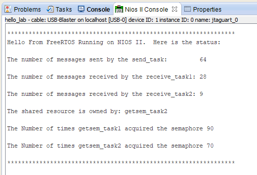
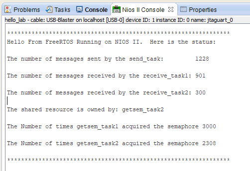
This code is an example of using FreeRTOS on a NIOS II processor. The program creates five tasks, a message queue, and a semaphore. The tasks compete for a shared resource using the semaphore. Two of the tasks add messages to the message queue at different rates, while the other two tasks pull messages from the queue at different rates. The fifth task simply prints status information every three seconds.
When the program is run, all five tasks are created and executed in parallel. The getsem_task1 and getsem_task2 tasks compete for ownership of the shared resource. They use a semaphore to do this. When one of these tasks acquires the semaphore, it sets the global variable sem_owner_task_name to its task name.
The send_task adds incrementing numbers to the message queue. If the queue is full, it waits one second before trying again. The receive_task1 and receive_task2 tasks pull messages from the queue at different rates. They increment the global variables number_of_messages_received_task1 and number_of_messages_received_task2, respectively, every time they receive a message.
Finally, the print_status_task prints the current values of several global variables every three seconds, including the number of messages sent, the number of messages received by each of the two receive tasks, the task that currently owns the semaphore, and how many times each of the two getsem tasks has acquired the semaphore.
xQueueSend and xQueueReceive
xQueueSend and xQueueReceive are two functions provided by FreeRTOS to allow inter-task communication via message queues.
xQueueSend is used to send a message to a message queue. It takes three parameters: a handle to the message queue to which the message will be sent, a pointer to the message data, and a timeout value. The timeout value determines how long the task will wait if the message queue is currently full.
If the message queue has space, the message is added to the queue, and pdPASS is returned.
If the queue is full, the function will wait for a specified amount of time for space to become available, and if the queue remains full for that time, it will return errQUEUE_FULL.
QueueHandle_t msgqueue;
...
(xQueueSend(msgqueue, (void *)&msg, 0) == pdPASS)
2
3
xQueueReceive is used to receive a message from a message queue. It takes three parameters: a handle to the message queue from which the message will be received, a pointer to a buffer that will hold the received message, and a timeout value. The timeout value determines how long the task will wait if there are no messages currently available in the message queue.
If a message is available, it is removed from the queue and copied into the buffer pointed to by the second parameter. The function returns pdPASS if a message was successfully received, and errQUEUE_EMPTY if the message queue was empty and the function timed out waiting for a message.
xQueueReceive(msgqueue, &msg, portMAX_DELAY);
It's important to note that both of these functions can block indefinitely if their respective timeouts are set to portMAX_DELAY, which will cause the task to block indefinitely until the queue operation can be completed. It is also worth mentioning that both of these functions can be called from within an interrupt service routine (ISR) by using the xQueueSendFromISR and xQueueReceiveFromISR variants, respectively.
# Do it yourself: Create a Counting Task
Now, try and modify the example program so that your system increments a counter and displays it on the seven-segment displays of the DE2-115.
Hints:
- You will need a function to access the PIO peripheral. Add the heade r for accessing PIO peripherals.
- You will need to define a new task priority with the lowest priority
- Create the task body, and make the task wait for 1 second before incrementing the count
void counter_task(void *pvParameters){
    int counter = 0;
    while(1)
    {
        counter++;
        // write a value to the seven-segment display
        // make the task delay for 1 second
    }
}
2
3
4
5
6
7
8
9
- Add a function call to create the task in the
initCreateTasks(void)function:
xTaskCreate(
    counter_task,           // the function used to be task
    "counter_task",         // the name of the task, for debugging purpose
    TASK_STACKSIZE,         // the size of the stack
    NULL,                   // the parameter passed to the task, in this case, none.
    counter_task_priority,  // the priority of the task
    NULL                    // task handler, which can be used to delete the task
);
2
3
4
5
6
7
8
Now build the application and run it to see if it works. You can use the freertos_counter.c file of the freertos_counter directory in the resource package to verify your solution.