# COMPSYS 723 - Final Assessment - FIRST SEMESTER, 2018
- 1. Embedded Systems Software and Concurrency
- (a) State oriented models, activity oriented models, and structure oriented models are three categories of models of computation. Explain how each category of models of computation are used to specify system functionality. Provide an example for each category of models of computation.
- (b) Specifications must be validated for its completeness and correctness. Define what it means for a specification to be complete and correct.
- (c) List and briefly explain five desirable features of embedded systems specification languages.
- (d) The SystemJ language uses the GALS model of computation.
- (e) As are designer you are presented with two techniques for implementing an embedded application. They are; (1) the single program and (2) the foreground/background approaches. Briefly describe both approaches. You may use examples and pseudocode to aid your explanations. Name one advantage and one disadvantage for both approaches.
- 2. Real-time Operating Systems
- (a) List the four major mechanisms that can be used to ensure mutual exclusive access to shared resources.
- (b) There are two categories of rendezvous, unilateral and bilateral rendezvous.
- (c) When implementing rendezvous between a task and an ISR, would you use a unilateral or a bilateral rendezvous? Explain your choice.
- (d) Define what are reentrant functions and describe how you would program to ensure a function is reentrant.
- (e) For scheduling tasks, RTOS implements finite state machine for each task and manages its transitions. Draw the general state machine model of the task scheduling in a typical RTOS.
- 3. FreeRTOS and Scheduling
- (a) Tasks in FreeRTOS can be executed periodically or based on random events.
- (b) Consider the following set of tasks depicted in Table 1. For the following questions, assume all tasks are released at zero time and there are no context switching costs.
- (c) Priority inversion is a major issue when protecting shared resources in real-time systems.
- (d) Given an application that consists of three tasks that run under FreeRTOS as shown in Code 2. Note that the function creating a task has a parameter (prior to the last parameter) that sets the tasks priority.
- 4. Synchronous Programming in Esterel.
- 5. Statechart, Mealy machine, and concurrency.
- (a) Consider the two concurrent processes represented as a Statechart in Figure 5. Give the resultant composition (product) as a single Statechart. Signals a, b and c, are inputs from the environment.
- (b) Consider the two Mealy machines shown in Figure 6, running on a single processor. Signals b, q, and d are inputs from the environment, while a, c, e, and f are outputs. Symbol fg represents an empty set, i.e., no output emissions.
- 6. Safe State Machine and Esterel.
- (a) Develop the Safe State Machine (SSM) specification of ABCRO: \emit an output O when the three inputs A, B and C have happened. When input R happens, reset this behaviour while allowing the body to execute during this instant". What will be the outputs in the following instants.
- (b) Write an equivalent Esterel module for the Safe State Machine (SSM) developed above. A, B, C and R are input signals from the environment and O is an output signal.
# 1. Embedded Systems Software and Concurrency
Questions:
Embedded real-time systems can be implemented using a range of techniques and they can be specified using various models of computation.
# (a) State oriented models, activity oriented models, and structure oriented models are three categories of models of computation. Explain how each category of models of computation are used to specify system functionality. Provide an example for each category of models of computation.
Answer
State-Oriented Models: State-oriented models, such as Finite State Machines (FSM) and Statecharts, represent the system in terms of its states and the events or conditions that cause transitions between states. These models are particularly useful in designing systems where the operation is dependent on its current state, or status, and the occurrence of specific events.
For example, consider a simple digital lock system. The states could include 'Locked', 'Unlocked', and 'Alarm'. The input (a correct or incorrect pin) determines the transitions. If the system is in the 'Locked' state and a correct pin is entered, it transitions to the 'Unlocked' state. If an incorrect pin is entered, it transitions to the 'Alarm' state.
Activity-Oriented Models: Activity-oriented models, such as Petri Nets or Dataflow models, focus on the actions or processes the system is performing, and how data moves through these processes. They are often used in systems where data processing and the ordering of events is a major concern.
For example, consider a manufacturing assembly line system. The activities might include: receiving raw materials, fabricating parts, assembling parts into products, and shipping the final product. Each of these activities is a node in the Petri net, with data (parts or products) flowing between them.
Structure-Oriented Models: Structure-oriented models, like Block Diagrams or Synchronous Data Flow Graphs (SDFG), represent the system in terms of its structural components and their interactions. They are particularly useful for systems that have a complex structure or that involve intricate interactions among components.
For example, consider a drone control system. This may be broken down into various structural components like the GPS module, altitude sensor, propeller control, camera system, etc. A block diagram would illustrate how data and control signals are passed between these components to achieve the desired functionality - navigation, altitude control, or capturing images.
Each model serves a different purpose, and the selection of a model depends on the nature of the system, the complexity of its functionality, and the primary concerns of its operation.
# (b) Specifications must be validated for its completeness and correctness. Define what it means for a specification to be complete and correct.
Answer
A specification, in the context of software or systems engineering, is a detailed description of the objectives, functionality, or the behavior of a system. Two critical attributes of a high-quality specification are completeness and correctness.
Completeness: A specification is complete when it provides a full and exhaustive description of the system's functionality, behavior, and constraints. This means that it includes all necessary details to guide the development, testing, and deployment of the system. For example, it should describe all relevant use cases, expected behaviors, error conditions, and any other necessary information for the design and implementation of the system. Incomplete specifications may lead to misunderstandings between stakeholders, missing functionality, or erroneous behavior.
Correctness: A specification is correct when it accurately describes the intended behavior and objectives of the system. It should not include any false or contradictory information. This means the described system would meet the requirements and goals of stakeholders if it were implemented as per the specification. Incorrect specifications can lead to systems that behave differently than intended or do not meet the stakeholders' needs.
In order to ensure that a specification is both complete and correct, it's usually necessary to go through several rounds of drafting, review, and revision. Techniques such as formal methods, model checking, simulation, and user or stakeholder review can be used to validate the completeness and correctness of a specification.
# (c) List and briefly explain five desirable features of embedded systems specification languages.
Answer
An effective embedded systems specification language should ideally possess the following features:
Expressiveness: A specification language should be expressive enough to describe all aspects of a system's behavior, including normal operation, edge cases, and error handling. It should support complex constructs and provide the ability to describe both low-level details and high-level system interactions.
Clarity and Readability: The language should be clear and easy to understand. Good readability helps developers, testers, and other stakeholders comprehend the specification and reduces the chances of misinterpretation, which can lead to defects in the system.
Precision and Unambiguity: The language should be precise and unambiguous to avoid any misunderstandings. This is particularly important for complex or safety-critical systems, where even minor misinterpretations can have serious consequences.
Verifiability: It's crucial for the specification language to be verifiable. This allows formal methods, simulations, or other techniques to be used to check that the specification is consistent, complete, and correct. It also supports testing of the implemented system against the specification.
Modularity: Modularity in a specification language allows parts of the specification to be developed, verified, and revised independently. This can simplify the development process, particularly for large or complex systems. It also improves maintainability, as changes can be made to one part of the specification without impacting others.
Standardization: A standardized language aids in collaboration and understanding across various teams or stakeholders. It also enables the use of common tools for editing, analyzing, and testing the specifications.
Integration with Development Tools: The language should be compatible or integrable with common development tools. This could include design tools, compilers, simulation tools, or version control systems. Such integration can improve efficiency and reduce the chances of errors.
These features can significantly enhance the efficiency and reliability of the system development process, and help ensure that the resulting system meets its requirements and performs reliably.
# (d) The SystemJ language uses the GALS model of computation.
(i) Explain and describe the GALS model of computation. You may use SystemJ entities as examples.
(ii) Describe the mechanism (objects) used for communication:
- For reactions within the same clock domain.
- For reactions across different clock domains.
Answer
(i) GALS Model of Computation
GALS (Globally Asynchronous Locally Synchronous) is a model of computation used in SystemJ and other system design languages. It is a model used for designing systems that are globally asynchronous (meaning that different parts of the system can operate independently of one another and are not required to synchronize globally) but locally synchronous (meaning that within each sub-system, operations are synchronized).
In the context of SystemJ, the entire system is composed of multiple synchronous islands (referred to as clock domains) operating independently at their own pace. Each clock domain can be viewed as a synchronous finite state machine. These islands communicate with each other asynchronously.
(ii) Mechanism Used for Communication
Communication within the same clock domain:
Within a single clock domain, the communication between different parts of the system is synchronized as per the local clock, meaning all the operations within this clock domain are performed in a synchronized way according to the clock ticks. The communication is direct and there's no need for special handshaking protocols or other synchronization mechanisms. SystemJ uses signals within the same clock domain for communication, enabling different parts to share information.
Communication across different clock domains:
For communication across different clock domains, SystemJ uses a mechanism called channels. Channels are asynchronous and facilitate communication between different clock domains. Since different clock domains operate independently, the source clock domain sends the data when it's ready, and the destination clock domain reads the data when it's ready. SystemJ uses handshaking protocols to ensure safe data transfer across clock domains.
It's also worth noting that communication across clock domains needs to handle issues that don't arise within a single domain. For example, there might be cases where one domain is sending data more quickly than another can receive it, leading to potential data loss. SystemJ and the GALS model provide mechanisms to manage these situations and ensure reliable communication between different parts of the system.
# (e) As are designer you are presented with two techniques for implementing an embedded application. They are; (1) the single program and (2) the foreground/background approaches. Briefly describe both approaches. You may use examples and pseudocode to aid your explanations. Name one advantage and one disadvantage for both approaches.
Answer
- Single Program Approach: In the single program approach, the entire functionality of the embedded system is implemented within a single continuous loop. This loop runs endlessly, constantly polling for input, processing data, and controlling output.
Example (Pseudocode):
initialize_system()

while True:
    read_inputs()
    process_data()
    control_outputs()
2
3
4
5
6
Advantage: Simplicity. It's easy to understand, design, and debug, especially for simple systems.
Disadvantage: Poor responsiveness and lack of scalability. It can only do one thing at a time and must complete each operation before it can check for new inputs. As the complexity of the system grows, managing this in a single loop becomes inefficient and potentially unmanageable.
- Foreground/Background Approach: In this approach, the system is divided into two parts: the background loop and one or more foreground tasks (often triggered by interrupts). The background loop is similar to the single program approach, continuously polling for inputs and controlling outputs. Foreground tasks are usually time-critical operations that are triggered by specific events or interrupts and temporarily preempt the background loop.
Example (Pseudocode):
initialize_system()

set_interrupt_handler() # Sets a function to be called when an interrupt occurs

while True:
    read_inputs() # Background task
    process_data() # Background task
    control_outputs() # Background task

def interrupt_handler():
    handle_interrupt() # Foreground task
2
3
4
5
6
7
8
9
10
11
Advantage: Improved responsiveness. The system can respond quickly to important events by temporarily interrupting less time-critical operations.
Disadvantage: Increased complexity. Managing multiple tasks and ensuring safe and correct behavior when interrupts occur can be challenging. There is also the risk of problems like missed interrupts or priority inversion, where a lower-priority task blocks a higher priority one.
# 2. Real-time Operating Systems
Questions:
Real-Time Operating Systems (RTOS) allows specification of two types of software behaviors, tasks and interrupt service routines (ISR). Sharing of resources and communication between these is a key issue when designing real-time applications.
# (a) List the four major mechanisms that can be used to ensure mutual exclusive access to shared resources.
(i) For each mechanism describe how they can ensure mutually exclusive access to shared resources.
(ii) Name one advantage and one disadvantage for each mechanism.
Answer
Mutual exclusion in concurrent systems, such as those managed by a Real-Time Operating System (RTOS), is crucial to avoid data inconsistency and race conditions. Here are four common mechanisms for ensuring mutual exclusive access to shared resources:
Semaphore
(i) A semaphore is a variable or abstract data type that provides a simple but effective means of controlling access to a shared resource. They can be binary (mutex), allowing only one task to access a resource, or counting, allowing a certain number of tasks to access a resource simultaneously.
(ii) Advantage: Semaphores are simple to understand and can handle complex synchronization problems. They can also be used for signaling between tasks.
Disadvantage: They can be prone to common programming errors like priority inversion (lower priority task holding a resource needed by a higher priority task) and deadlock (two tasks each holding a resource the other needs).
Mutex (Mutual Exclusion)
(i) A mutex is a type of binary semaphore used to protect access to shared resources. A task must "lock" the mutex before using the shared resource and then "unlock" it when finished. If another task tries to lock the mutex while it's already locked, it will be blocked until the mutex is unlocked.
(ii) Advantage: Mutexes often include priority inheritance, which can help avoid priority inversion.
Disadvantage: They're only suitable for managing mutual exclusion. If used for task synchronization, they could lead to deadlocks.
Monitor
(i) Monitors are a high-level synchronization construct that allows only one task to access the shared resource at a time. They encapsulate the shared resource and the synchronization mechanisms (like a mutex) to control access to it.
(ii) Advantage: Monitors abstract the synchronization details, making the code easier to understand and less prone to errors.
Disadvantage: They require support from the programming language or runtime environment, which may not be available in all cases.
Critical Section
(i) Critical sections are portions of the code where a task accesses a shared resource. Access to critical sections is controlled by using other mechanisms (like semaphores or mutexes) to ensure that only one task can execute the critical section at a time.
(ii) Advantage: They offer fine-grained control over mutual exclusion, as they can be as small as a few instructions or as large as necessary.
Disadvantage: Determining the correct boundaries of critical sections can be difficult and error-prone. Too large, and they can unnecessarily block other tasks. Too small, and they may not effectively ensure mutual exclusion.
These mechanisms all provide ways to ensure that only one task can access a shared resource at a time, but each comes with its own benefits and drawbacks. The choice of mechanism depends on the specific requirements of the system being developed.
# (b) There are two categories of rendezvous, unilateral and bilateral rendezvous.
- Define unilateral and bilateral rendezvous.
- Explain how you would use semaphores to implement unilateral and bilateral rendezvous between two tasks. You may use pseudocode to aid your explanation.
Answer
Rendezvous is a synchronization method between two processes or tasks. Here is the definition for each type:
Unilateral Rendezvous: Unilateral rendezvous is a one-way synchronization, where one task must reach a certain point before the other task can proceed.
Bilateral Rendezvous: Bilateral rendezvous is a two-way synchronization, where both tasks must reach a certain point before either can proceed.
Here's an illustration of how you might use semaphores to implement these two types of rendezvous:
(i) Unilateral Rendezvous
We can implement unilateral rendezvous using a binary semaphore initialized to 0.
Pseudocode:
# Semaphore declaration
Semaphore sem = 0

# Task A
do_something_in_A()
sem.signal() # Let Task B proceed

# Task B
sem.wait() # Wait for Task A
do_something_in_B()
2
3
4
5
6
7
8
9
10
In this pseudocode, Task B waits for Task A to complete before it can proceed.
(ii) Bilateral Rendezvous
For bilateral rendezvous, we need two semaphores, one for each direction, both initialized to 0.
Pseudocode:
# Semaphore declarations
Semaphore semA = 0
Semaphore semB = 0

# Task A
do_something_in_A()
semA.signal() # Signal that A has reached the rendezvous point
semB.wait() # Wait for B to reach the rendezvous point

# Task B
do_something_in_B()
semB.signal() # Signal that B has reached the rendezvous point
semA.wait() # Wait for A to reach the rendezvous point
2
3
4
5
6
7
8
9
10
11
12
13
In this pseudocode, both Task A and Task B have to reach the rendezvous point before either can proceed. Each task signals its arrival at the rendezvous point and waits for the other task to arrive.
# (c) When implementing rendezvous between a task and an ISR, would you use a unilateral or a bilateral rendezvous? Explain your choice.
Answer
When implementing rendezvous between a task and an Interrupt Service Routine (ISR), you would generally use a unilateral rendezvous.
In a unilateral rendezvous, the task waits for the ISR to complete. Once the ISR is done (often after handling a hardware event), it signals the task which can then proceed with its operation. This makes sense as ISRs are typically responses to asynchronous hardware events such as a button press, data arriving over a network, or a timer expiring, and the main task needs to wait until the event has been handled before it can proceed.
The use of a bilateral rendezvous between a task and an ISR isn't typical because ISRs should be kept as short as possible to minimize the disruption to the main task. Having an ISR wait for a task to reach a certain point (as in bilateral rendezvous) would go against this principle. The ISR needs to complete quickly and not be held up waiting for another task to reach a certain point.
Hence, unilateral rendezvous is more suited to the task and ISR relationship where the task must wait for the ISR to signal that it has completed its job.
# (d) Define what are reentrant functions and describe how you would program to ensure a function is reentrant.
Answer
Reentrant Functions
A reentrant function is a function that can be safely called again before its previous invocation has been completed (i.e., it can be safely executed concurrently or reentered multiple times). Reentrancy is a property that is particularly important in concurrent and real-time programming, as well as in interrupt handlers.
Reentrant functions do not hold static data over successive calls, do not return a pointer to static data, and only modify local variables or their parameters. They also do not call non-reentrant functions.
To ensure a function is reentrant, you would follow these guidelines:
Avoid Global Variables: Do not use global or static variables because their values can be altered by different invocations of the function. If you must use them, ensure access to them is atomic or protected by a mutex or semaphore to ensure mutual exclusion.
Local Variables: Use local variables instead of global or static variables. Each invocation of a function gets its own separate copy of local variables stored on the stack.
Parameters: Pass all data to the function via parameters. This is a form of making data local to the function.
Thread-safe Libraries: Only use libraries or system calls that are thread-safe or reentrant.
Avoid non-reentrant Functions: Do not call other non-reentrant functions from within a reentrant function.
Atomic Operations: Make sure that any operation that updates memory is atomic, meaning it can't be interrupted. If an operation can't be made atomic, use a synchronization mechanism like a mutex to ensure safe access.
Immutable Data: Use immutable data structures or constants. These are inherently safe because they don't change.
By following these guidelines, you can ensure that a function is reentrant and safe to use in a concurrent or preemptive multitasking context.
# (e) For scheduling tasks, RTOS implements finite state machine for each task and manages its transitions. Draw the general state machine model of the task scheduling in a typical RTOS.
Answer
In a typical Real-Time Operating System (RTOS), each task or thread is represented as a finite state machine with several possible states, and the task scheduler manages the transitions between these states.
Below is a text-based illustration of a simple state machine model for task scheduling in an RTOS:
[Created] --(Scheduler starts task)--> [Ready]
^  |
|  v
|  [Suspended] --(Task resumed)-->
|
[Suspended]
^  |
|  v
|  [Blocked] --(Resource available)-->
|
[Running] --(Scheduler switches task)-->
^  |
|  v
|  [Terminated]
2
3
4
5
6
7
8
9
10
11
12
13
14
Here are the states in this model:
Created: A task enters this state when it is first initialized. The task's resources are allocated, but it isn't ready to run yet.
Ready: The task is ready to run and is waiting for the scheduler to give it CPU time.
Running: The task is currently being executed.
Blocked: The task is waiting for some resource to become available or an event to occur. The task cannot continue until this happens.
Suspended: The task has been paused, either by an external event or by the scheduler.
Terminated: The task has completed execution and its resources can be reclaimed.
This is a simplified model, and real systems might have additional states and transitions depending on the complexity of the system. However, this gives a general idea of how task scheduling in an RTOS works.
# 3. FreeRTOS and Scheduling
Questions:
FreeRTOS is an open-source operating system that you used during your assignment. It provided many useful features for communicating, resource management and scheduling. Answer the following questions.
# (a) Tasks in FreeRTOS can be executed periodically or based on random events.
(i) Name the FreeRTOS mechanism you would use to describe periodic tasks? Write pseudocode snippet for a periodic task (of any period) in FreeRTOS.
(ii) How would you use FreeRTOS to facilitate event driven tasks? Write pseudocode snippet for an event driven task. You can assume the event will cause an ISR (i.e., exampleISR()) to execute.
Specification for a set of tasks:
| Task | Period (ms) | Execution Time (ms) |
|---|---|---|
| t1 | 100 | 10 |
| t2 | 500 | 20 |
| t3 | 700 | 10 |
| t4 | 900 | 30 |
| t5 | 200 | 50 |
Answer
(i) In FreeRTOS, you can describe periodic tasks using the vTaskDelayUntil() function, which causes a task to block until a specified period has passed. This function is used to implement periodic tasks with a fixed frequency.
Here's a pseudocode example of a periodic task in FreeRTOS:
void periodicTask(void *pvParameters)
{
    TickType_t xLastWakeTime;
    const TickType_t xFrequency = pdMS_TO_TICKS(100);  // Period of 100 ms

    // Initialize the xLastWakeTime variable with the current time.
    xLastWakeTime = xTaskGetTickCount();

    while(1)
    {
        // Wait for the next cycle.
        vTaskDelayUntil(&xLastWakeTime, xFrequency);

        // Perform the task
        performTask();
    }
}
2
3
4
5
6
7
8
9
10
11
12
13
14
15
16
17
This code creates a task that will execute performTask() every 100 milliseconds.
(ii) FreeRTOS facilitates event-driven tasks with the use of queues, semaphores, and event groups. In the case of an ISR triggering a task, you can use a binary semaphore.
Here's a pseudocode example of an event-driven task with an ISR in FreeRTOS:
SemaphoreHandle_t xSemaphore = NULL;

void exampleISR(void)
{
    BaseType_t xHigherPriorityTaskWoken = pdFALSE;
    xSemaphoreGiveFromISR(xSemaphore, &xHigherPriorityTaskWoken);
    portYIELD_FROM_ISR(xHigherPriorityTaskWoken);
}

void eventDrivenTask(void *pvParameters)
{
    xSemaphore = xSemaphoreCreateBinary();

    while(1)
    {
        if(xSemaphoreTake(xSemaphore, portMAX_DELAY) == pdTRUE)
        {
            // The semaphore has been taken, meaning the ISR has occurred.
            handleEvent();
        }
    }
}
2
3
4
5
6
7
8
9
10
11
12
13
14
15
16
17
18
19
20
21
22
In this code, the exampleISR() function gives a semaphore from an interrupt context, and the eventDrivenTask() function takes the semaphore, waiting indefinitely if necessary. When the semaphore is available, it means an event (the interrupt) has occurred and the task then proceeds to handle the event.
Regarding the task specification you provided, it's important to note that the total CPU usage must not exceed 100%. In this case, for instance, if tasks t1 to t5 were all to execute at their highest frequency simultaneously, the execution time (or CPU usage) would be beyond 100% ((10/100 + 20/500 + 10/700 + 30/900 + 50/200) * 100 = 120%), which is not feasible. Consequently, tasks execution, scheduling policy, and task priority should be carefully designed.
# (b) Consider the following set of tasks depicted in Table 1. For the following questions, assume all tasks are released at zero time and there are no context switching costs.
(i) Assign priorities to each task using rate monotonic scheduling where a higher integer means a higher priority.
(ii) If you were to schedule the tasks using cyclic executive scheduling, when will task t2 first begin executing? Use the priorities you have assigned in (i) and assume higher priority tasks are scheduled first.
(iii) If you were to schedule the tasks using round-robin scheduling, when will task t2 first begin executing? Use the priorities you have assigned in (i) and assume higher priority tasks are scheduled first. The round-robin time slice is 10ms.
(iv) State two advantages of cyclic executive scheduling.
Answer
(i) In Rate Monotonic Scheduling (RMS), tasks are assigned priorities based on their period: the shorter the period, the higher the priority. Given the tasks:
| Task | Period (ms) | Execution Time (ms) |
|---|---|---|
| t1 | 100 | 10 |
| t2 | 500 | 20 |
| t3 | 700 | 10 |
| t4 | 900 | 30 |
| t5 | 200 | 50 |
The priority assignment (from highest to lowest) would be:
| Priority (higher number means higher priority) | Task | Period (ms) | Execution Time (ms) |
|---|---|---|---|
| 5 | t1 | 100 | 10 |
| 4 | t5 | 200 | 50 |
| 3 | t2 | 500 | 20 |
| 2 | t3 | 700 | 10 |
| 1 | t4 | 900 | 30 |
(ii) Under cyclic executive scheduling (also known as static time-driven scheduling), tasks are scheduled in a repeating sequence based on their priorities. In the first cycle:
- t1 will execute first and take 10ms
- t5 will execute next and take 50ms
So at 60ms, both t1 and t5 have completed execution. t2 (the next highest priority task) would begin executing at this point.
(iii) In a round-robin scheduling scheme, tasks are given equal fixed-length time slices or quantum in a cyclic way. Assuming the priorities from (i) and a time slice of 10ms, the tasks would execute in the following order:
- t1 executes for 10ms (completes)
- t5 executes for 10ms
- t2 executes for 10ms
- t3 executes for 10ms
- t4 executes for 10ms
- t5 executes for its second 10ms
So, t2 will first begin executing at 30ms into the schedule, after t1 and the first slice of t5.
(iv) Two advantages of cyclic executive scheduling are:
Deterministic behavior: It is easy to predict when each task will run, which can be an advantage in real-time systems where meeting timing deadlines is critical.
Low overhead: Because there is no task preemption (except by higher-priority interrupt routines) and tasks run to completion, there's no need to save and restore task context. This minimizes the overhead of context switching, making cyclic executive scheduling efficient for small systems with stringent timing requirements.
# (c) Priority inversion is a major issue when protecting shared resources in real-time systems.
(i) Using the provided example, explain why priority inversion can be a serious issue for real-time systems.
(ii) What mechanism does FreeRTOS provide to mitigate priority inversion? Name both the FreeRTOS programming construct and the technique. Explain how this technique can help mitigate the effects of priority inversion. You may use the example to aid your explanation.
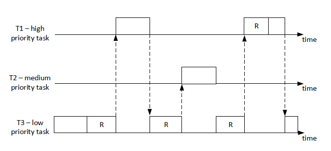
Figure 1 provides a timing diagram illustrating an example of priority inversion.
Answer
(i) Priority inversion is a situation in real-time systems where a higher priority task is indirectly preempted by a lower priority task effectively "inverting" their relative priorities. This scenario can be a significant problem in real-time systems because it can lead to missed deadlines of high-priority tasks, creating system instability or failure.
Looking at the provided timing diagram, we see that Task High (H) has a higher priority than both Task Mid (M) and Task Low (L). However, while Task H is waiting for a resource held by Task L, Task M preempts the execution. Task L can't finish and release the resource because it's blocked by Task M. Therefore, Task H can't proceed even though it's the highest priority task. This delay for Task H is the priority inversion.
(ii) FreeRTOS provides a mechanism called Priority Inheritance to mitigate the problem of priority inversion. This is implemented through FreeRTOS's Mutexes.
In Priority Inheritance, when a high-priority task is blocked by a lower priority task (because the lower priority task holds a mutex needed by the high-priority task), the priority of the task holding the mutex is temporarily raised to the priority of the higher-priority task. This prevents medium-priority tasks from preempting the execution, allowing the lower-priority task to finish and release the resource more quickly.
Applying this to the example, when Task H is blocked and Task L holds the resource, the priority of Task L is raised to that of Task H. Now, Task M can't preempt Task L because Task L effectively has high priority. Task L can complete its job, release the resource, and its priority is returned to normal. Task H can then acquire the resource and proceed. This reduces the window of priority inversion and ensures high-priority tasks can complete within their expected timeframes.
# (d) Given an application that consists of three tasks that run under FreeRTOS as shown in Code 2. Note that the function creating a task has a parameter (prior to the last parameter) that sets the tasks priority.
(i) Describe how the tasks will execute on a single core processor. Use the line numbers to aid your explanation. (hint: look at the tasks priorities; put yourself into a role of the scheduler).
(ii) Write the (printf) output of the application.
Code 02:
#define LONG_TIME 0xffff
SemaphoreHandle_t sem;
TaskHandle_t hTask1, hTask2, hTask3;
void myPrint(char* str) {
    vTaskDelay(100);
    if (xSemaphoreTake(sem, LONG_TIME) == pdTRUE) {
        printf("%s", str);
        xSemaphoreGive(sem);
    }
}

void Task1(void *pvParameters) {
    myPrint("Hello 1\n");
    vTaskDelete(NULL);
}

void Task2(void *pvParameters) {
    vTaskDelete(hTask1);
    myPrint("Hello 2\n");
    vTaskDelete(NULL);
}

void Task3(void *pvParameters) {
    vTaskPrioritySet(hTask2, 4);
    myPrint("Hello 3\n");
    vTaskDelete(NULL);
}

int main(int argc, char **argv) {
    sem = xSemaphoreCreateBinary();
    xSemaphoreGive(sem);
    BaseType_t xR;
    xR = xTaskCreate(Task1, "T1", 500, NULL, 1, &hTask1);
    xR = xTaskCreate(Task2, "T2", 500, NULL, 2, &hTask2);
    xR = xTaskCreate(Task3, "T3", 500, NULL, 3, &hTask3);
    vTaskStartScheduler();
    for (;;);
}
2
3
4
5
6
7
8
9
10
11
12
13
14
15
16
17
18
19
20
21
22
23
24
25
26
27
28
29
30
31
32
33
34
35
36
37
38
Answer
(i) Considering the priority of each task and how FreeRTOS scheduler operates, the sequence of execution will be as follows:
main()function starts and creates a binary semaphore. It then creates three tasks,Task1,Task2, andTask3, with priorities 1, 2, and 3, respectively. The scheduler will be in a ready state with all three tasks.After creating the tasks,
main()function starts the scheduler withvTaskStartScheduler(). Because Task3 has the highest priority (3), it will start executing first.Inside
Task3, it first sets the priority ofTask2to 4. Then it callsmyPrint()with the string "Hello 3\n".myPrint()has a delay of 100ms, after which it will take the semaphore, print "Hello 3\n", and then give the semaphore back. Finally,Task3deletes itself.After
Task3is deleted, the next highest priority task isTask2, which now has a priority level of 4 due to the modification inTask3.Task2starts executing and first deletesTask1before it gets a chance to run. Then it callsmyPrint()with the string "Hello 2\n". Similar to before,myPrint()causes a delay, takes the semaphore, prints "Hello 2\n", gives back the semaphore, and thenTask2deletes itself.At this point,
Task1has already been deleted, andTask2andTask3have completed their executions and deleted themselves. So, no more tasks are left to be executed.
(ii) The output of the application will be:
Hello 3
Hello 2
2
First, Task3 prints "Hello 3\n", and then Task2 prints "Hello 2\n". Task1 is deleted by Task2 before it gets a chance to execute and print "Hello 1\n", so we do not see "Hello 1\n" in the output.
# 4. Synchronous Programming in Esterel.
Questions:
(a) Consider the program given in Code 3. What is wrong with this program and how to fix the problem?
Code 3:
module noncausal:
signal A, B, C in
    loop
    [
        present C then emit A;
        end present;
        pause;
    ]
    ||
    [
        await A;
        emit B;
    ]
    ||
    [
        await B;
        emit C;
    ]
    end loop
 end signal
 end module
2
3
4
5
6
7
8
9
10
11
12
13
14
15
16
17
18
19
20
21
Answer
The program in Code 3 defines a non-causal loop. That is, it has a circular dependency without a delay, which makes it impossible to determine an execution order for the statements.
The problem arises from the signals A, B, and C. Inside the loop, A is emitted when C is present, B is emitted after A is awaited, and C is emitted after B is awaited. This results in a circular dependency: C -> A -> B -> C.
To resolve this, we need to break the circular dependency by introducing a delay. This can be done by changing the order of operations or introducing another pause statement.
Here's one way to fix it:
module causal:
signal A, B, C in
    loop
    [
        await tick;
        present C then emit A;
        end present;
    ]
    ||
    [
        await A;
        emit B;
    ]
    ||
    [
        await B;
        emit C;
    ]
    end loop
 end signal
 end module
2
3
4
5
6
7
8
9
10
11
12
13
14
15
16
17
18
19
20
21
In this fixed version, a pause statement is added before A is emitted. This means that on the first cycle of the loop, A cannot be emitted because C is not yet present. A will be emitted only on the subsequent cycles if C was emitted in the previous cycle, breaking the non-causal loop.
# (b) Express the Esterel code segment in Code 4 using pure (primitive) kernel statements. Signals I and Q, are inputs from the environment, while M is an output.
Code 4:
loop
    abort
        sustain M
    when Q
each I
2
3
4
5
Answer
loop
    abort
        abort
            loop
                emit M;
                pause;
            end loop
        when Q
        halt;
    when I
end loop
2
3
4
5
6
7
8
9
10
11
In this code:
we used the expansions of the derived statement sustain s and loop p each s:
sustain s
loop
    emit s;
    pause
end
2
3
4
loop p each s
loop
    abort
        p;
        halt;
    when s
end loop
2
3
4
5
6
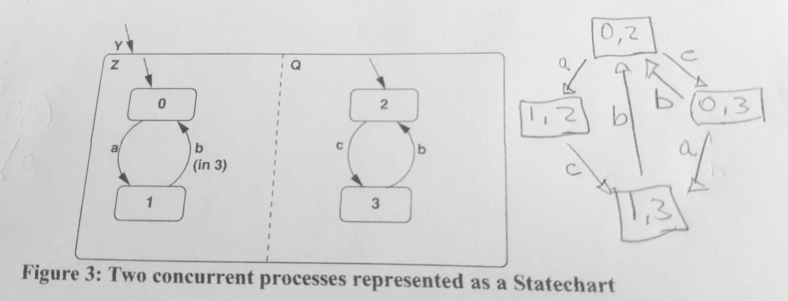
# 5. Statechart, Mealy machine, and concurrency.
Questions:
# (a) Consider the two concurrent processes represented as a Statechart in Figure 5. Give the resultant composition (product) as a single Statechart. Signals a, b and c, are inputs from the environment.
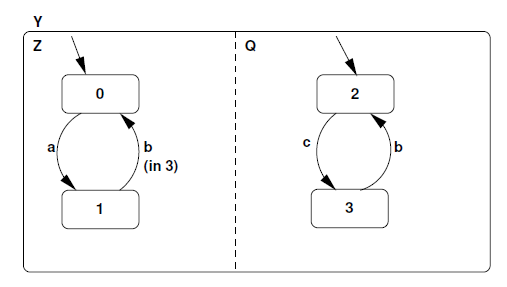
Figure 5: Two concurrent processes represented as a Statechart
Answer
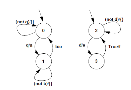
# (b) Consider the two Mealy machines shown in Figure 6, running on a single processor. Signals b, q, and d are inputs from the environment, while a, c, e, and f are outputs. Symbol fg represents an empty set, i.e., no output emissions.
(i) Compute the concurrent asynchronous parallel composition (product) of the two Mealy machines.
(ii) Compute the concurrent synchronous parallel composition (product) of the two Mealy machines.
# 6. Safe State Machine and Esterel.
Questions:
# (a) Develop the Safe State Machine (SSM) specification of ABCRO: \emit an output O when the three inputs A, B and C have happened. When input R happens, reset this behaviour while allowing the body to execute during this instant". What will be the outputs in the following instants.
(i) Tick 1, Input A:
(ii) Tick 2, Input B, C, R:
(iii) Tick 3, Input B, R:
(iv) Tick 4, Input A, C:
(v) Tick 5, Input B, C, R:
Answer
First, let's define the Safe State Machine (SSM) for the ABCRO behavior. We need to account for inputs A, B, C, and R, and emit the output O when A, B, and C have all happened. If input R happens, it resets the state machine.
A possible SSM can be defined with 5 states:
Start: The initial state.GotA: The state after receiving input A.GotAB: The state after receiving inputs A and B.GotABC: The state after receiving inputs A, B, and C.Reset: The state after receiving input R.
Transitions between these states occur on receiving the relevant inputs. The Reset state transitions back to Start on the next tick.
Start --(A)--> GotA --(B)--> GotAB --(C)--> GotABC --(O is emitted)
  |             |              |               |
  (R)           (R)            (R)             (R)
  V             V              V               V
Reset <--(tick)- Reset <--(tick)- Reset <--(tick)- Reset
2
3
4
5
Now, let's simulate the SSM based on the inputs given in the question:
(i) Tick 1, Input A: The state machine starts in the Start state. Upon receiving input A, it transitions to the GotA state. No output is emitted.
(ii) Tick 2, Input B, C, R: The state machine is in the GotA state. Normally, receiving input B would transition it to the GotAB state, and then receiving C would transition it to the GotABC state, emitting output O. However, the R input also happens in this tick, so the state machine is reset before output O can be emitted. It moves to the Reset state, and will return to the Start state in the next tick.
(iii) Tick 3, Input B, R: The state machine is back in the Start state. The input B doesn't have any effect in this state, but the R input causes it to transition to the Reset state. It will return to Start state in the next tick. No output is emitted.
(iv) Tick 4, Input A, C: The state machine is back in the Start state. Upon receiving input A, it transitions to the GotA state. Input C doesn't have any effect in this state. No output is emitted.
(v) Tick 5, Input B, C, R: The state machine is in the GotA state. Upon receiving input B, it would transition to the GotAB state, but the R input also happens in this tick, causing the state machine to be reset before it can emit output O. It moves to the Reset state, and will return to the Start state in the next tick. No output is emitted.
So in this sequence of inputs, output O is never emitted.
# (b) Write an equivalent Esterel module for the Safe State Machine (SSM) developed above. A, B, C and R are input signals from the environment and O is an output signal.
Answer
The following Esterel module implements the Safe State Machine (SSM) developed above:
module ABCRO:
input A, B, C, R;
output O;
signal S1, S2, S3, S4 in
    loop
        [
            present A then emit S1;
            await R;
        ]
        ||
        [
            await S1;
            present B then emit S2;
            await R;
        ]
        ||
        [
            await S2;
            present C then emit S3;
            await R;
        ]
        ||
        [
            await S3;
            emit O;
            await R;
        ]
    end loop
end module
2
3
4
5
6
7
8
9
10
11
12
13
14
15
16
17
18
19
20
21
22
23
24
25
26
27
28
29
In this Esterel module:
- We use internal signals
S1,S2,S3, andS4to represent states in the state machine. - Each section of the parallel operator corresponds to a state transition in the state machine.
- For each section, we await the signal corresponding to the current state, then check if the next input is present and if so, emit the signal for the next state.
- If input
Ris present, execution jumps to the next cycle of the loop, effectively resetting the state machine. - When the state machine is in the
GotABCstate (signified by the presence ofS3), it emits outputO.