# COMPSYS 723 - Final Assessment - SEMESTER ONE 2019
- 1. Embedded systems and concurrency.
- (a) What are three basic techniques of organizing software modules (tasks) on bare-bone processors? Describe each of them in terms of symmetry, concurrency and control flow. Comment how they compare each to the other in terms of complexity of their implementation and capabilities. For illustration use two modules called A and B.
- (b) What are the differences of memory shared and message passing inter-process communication? Illustrate on small snapshots of pseudo-code where two processes are in producer/consumer type of relationship. When is it appropriate to use one or the other technique?
- (c) Define unilateral and bilateral rendezvous and give an example of its implementation by using semaphores and pseudo-code. When would you use each and why?
- (d) What are the potential issues when using semaphores and explain how to avoid them. Illustrate two of these problems, the deadlock and priority inversion in systems with tasks priorities using a timing diagram. How the priority inversion can be mitigated in an RTOS such as FreeRTOS?
- 2. Concurrent system use case.
- (a) Describe system organization if you implement it as a single program using pseudocode. How will you describe timing constraints that will guarantee correct system operation in this case?
- (b) What are the problems which must be addressed in this type of system implementation (reflect on mutual dependence of the tasks, rates at which tasks are executed).
- (c) If the software system is organized using foreground/background approach, describe its organization using pseudo-code. Clearly show and explain why some of the tasks are run in foreground and some in background. How will you describe timing constraints that will guarantee correct system operation in this case?
- (d) How would this system be affected if implemented as a multi-tasking system? Describe it with a task diagram and pseudo-code. How would you assign priorities to the tasks and how would you differentiate between periodic and aperiodic tasks?
- 3. Concurrent language and RTOS based concurrency.
- (a) Describe Globally Asynchronous Locally Synchronous (GALS) concurrency model of SystemJ and the use of synchronous and asynchronous processes in it. Introduce notions of reactions and clock-domains. Use a simple graphical representation to illustrate SystemJ program with two clock domains that each have two synchronous reactions. The list of SystemJ kernel statements is given in Table 1.
- (b) Make a conceptual design of the system controller from Question 2 using SystemJ (represent it first as a block diagram). Assume that there are two input signals into the program, the timer tick and string (Java type string) that represents an operator input, and single output signal represented by a string (Java type string) that needs to be displayed. Demonstrate the use of SystemJ communication and synchronization mechanisms between concurrent design entities.
- (c) Given an application that consists of 3 tasks that run under FreeRTOS as described below. Note that the function of creation a task has a parameter (prior to the last parameter) that sets the task’s priority.
- 4. Synchronous programming in Esterel.
- 5. Statechart, Mealy machine, and concurrency.
- 6. Safe State Machine, Statechart, and Mealy machine.
- (a) Give an equivalent single (flat) Mealy machine representation for the three concurrent processes represented as a Safe State Machine (SSM) in Figure 4. A, B, and C are input signals from the environment and O is an output signal.
- (b) List at least two differences and two similarities between Statechart and Safe State Machine (SSM).
# 1. Embedded systems and concurrency.
Questions:
Embedded and real-time systems are most often implemented on resource constrained platforms and typically consist of a set of functions implemented as software modules that are activated by external events, triggered by timers or by other functions.
# (a) What are three basic techniques of organizing software modules (tasks) on bare-bone processors? Describe each of them in terms of symmetry, concurrency and control flow. Comment how they compare each to the other in terms of complexity of their implementation and capabilities. For illustration use two modules called A and B.
Answer
There are several ways to organize software modules (tasks) on bare-bone processors, but for the purposes of your question, we'll consider three basic techniques: Sequential, Cooperative, and Preemptive multitasking.
Sequential Execution (Run-to-completion): This is the simplest form of task organization. In this model, Module A runs to completion before Module B begins. There is no concurrency or task switching involved.
Symmetry: This model is asymmetric, as the order of execution is strictly defined and not interchangeable (A then B).
Concurrency: There is no concurrency as tasks do not run simultaneously but sequentially.
Control flow: The control flow is linear, going from the start of Module A to the end of Module B.
Implementation Complexity: This model is the simplest to implement as it does not require complex operating system services such as task switching or scheduling. However, it is also the least flexible, and does not handle scenarios where Module B needs to execute while Module A is still running.
Cooperative Multitasking (Non-Preemptive multitasking): In this model, both Module A and Module B can start and run, but the switch from one module to the other only occurs when the running module voluntarily yields control.
Symmetry: This model can be either symmetric or asymmetric, depending on how tasks yield control to each other.
Concurrency: There is logical concurrency (although not physical concurrency), as both Module A and B can be in progress at the same time.
Control flow: The control flow can switch back and forth between Module A and B, but only when a module voluntarily yields control.
Implementation Complexity: This model is more complex than sequential execution as it requires some form of task switching. However, it is simpler than preemptive multitasking, and it allows for more flexibility in handling multiple tasks.
Preemptive Multitasking: This is the most complex model. Here, both Module A and Module B can start and run, and the system (or a scheduler) can switch tasks at any point, not just when a task voluntarily yields control.
Symmetry: This model is symmetric, as Module A and Module B have equal potential to be run and to be interrupted.
Concurrency: Similar to cooperative multitasking, there is logical concurrency, but also the potential for physical concurrency on multi-core or multi-processor systems.
Control flow: The control flow can switch back and forth between Module A and B at any time, based on the scheduler's decisions.
Implementation Complexity: This model is the most complex to implement, as it requires advanced operating system services like preemptive task switching and scheduling. However, it also provides the highest degree of flexibility and responsiveness, and it is the model used by most modern operating systems.
Remember, while the complexity increases from sequential to cooperative to preemptive multitasking, so does the flexibility and capability of the system to handle different scenarios and optimize system responsiveness and throughput. Each model has its appropriate use cases, and the choice of model depends on the specific requirements of the system being designed.
# (b) What are the differences of memory shared and message passing inter-process communication? Illustrate on small snapshots of pseudo-code where two processes are in producer/consumer type of relationship. When is it appropriate to use one or the other technique?
Answer
Inter-process communication (IPC) is a mechanism that allows processes to communicate and synchronize their actions. There are several ways to implement IPC, two of which are shared memory and message passing.
Shared Memory: In the shared memory model, a memory region is made accessible to multiple processes, allowing them to read and write data to that region. This method requires a means of synchronization (like semaphores or mutexes) to prevent race conditions and ensure data integrity.
Consider this simple pseudo-code example where a producer process writes data to a shared buffer, and a consumer process reads from it:
// Shared Memory Buffer
struct {
    int data;
    semaphore sem;
} shared_buffer;

// Producer Process
void producer() {
    while(true) {
        wait(shared_buffer.sem); // Wait until buffer is empty
        shared_buffer.data = produce_data();
        signal(shared_buffer.sem); // Signal that buffer is full
    }
}

// Consumer Process
void consumer() {
    while(true) {
        wait(shared_buffer.sem); // Wait until buffer is full
        consume_data(shared_buffer.data);
        signal(shared_buffer.sem); // Signal that buffer is empty
    }
}
2
3
4
5
6
7
8
9
10
11
12
13
14
15
16
17
18
19
20
21
22
23
Message Passing: In the message passing model, processes communicate by sending and receiving messages. This model does not require explicit synchronization as the send and receive operations are atomic.
Here is a simple pseudo-code example of the same producer/consumer scenario, using message passing:
// Producer Process
void producer() {
    while(true) {
        int data = produce_data();
        send(consumer, data);
    }
}

// Consumer Process
void consumer() {
    while(true) {
        int data;
        receive(producer, &data);
        consume_data(data);
    }
}
2
3
4
5
6
7
8
9
10
11
12
13
14
15
16
When to use which model depends on several factors:
Complexity: Message passing is generally easier to implement and reason about because it does not require explicit synchronization. However, for large volumes of data, the overhead of message passing can be prohibitive.
Performance: Shared memory can be faster because it avoids the overhead of kernel system calls and data copying. However, incorrect synchronization can lead to errors that are difficult to debug.
Scalability: Message passing scales better to distributed systems where processes run on different machines, as shared memory is typically not possible in such scenarios.
Modularity: Message passing promotes better modularity and separation of concerns, as processes do not need to agree on a shared data structure.
Generally, shared memory can be a good choice for high-performance applications on a single machine where processes need to share large amounts of data. On the other hand, message passing can be a better choice for distributed systems, or for simpler and more modular applications.
# (c) Define unilateral and bilateral rendezvous and give an example of its implementation by using semaphores and pseudo-code. When would you use each and why?
Answer
Rendezvous is a pattern of inter-process communication where two processes, or threads, synchronize with each other at a certain point of execution. The two main types of rendezvous are unilateral and bilateral.
- Unilateral Rendezvous: In a unilateral rendezvous, one process or thread waits for another to reach a certain point in its execution. The waiting process cannot proceed until the other process reaches the rendezvous point.
Here's a pseudo-code example illustrating unilateral rendezvous using semaphores:
// semaphore initially set to 0
semaphore sem = 0;

// Process A
void processA() {
    // ... do some work ...
    signal(sem); // Signal that work is done
    // ... continue work ...
}

// Process B
void processB() {
    // ... do some work ...
    wait(sem); // Wait for Process A to signal
    // ... continue work ...
}
2
3
4
5
6
7
8
9
10
11
12
13
14
15
16
In this example, Process B can't proceed past the wait(sem) line until Process A has called signal(sem). This is a unilateral rendezvous because only Process B is waiting for Process A.
- Bilateral Rendezvous: In a bilateral rendezvous, two processes or threads wait for each other. Neither process can proceed until both have reached the rendezvous point.
Here's a pseudo-code example illustrating bilateral rendezvous using semaphores:
// semaphores initially set to 0
semaphore semA = 0;
semaphore semB = 0;

// Process A
void processA() {
    // ... do some work ...
    signal(semB); // Signal that A is ready
    wait(semA); // Wait for B to be ready
    // ... continue work ...
}

// Process B
void processB() {
    // ... do some work ...
    signal(semA); // Signal that B is ready
    wait(semB); // Wait for A to be ready
    // ... continue work ...
}
2
3
4
5
6
7
8
9
10
11
12
13
14
15
16
17
18
19
In this example, neither process can proceed past the wait() line until the other process has called signal(). This is a bilateral rendezvous because both processes are waiting for each other.
When to use each:
Use a unilateral rendezvous when one process needs to wait for another process to complete some work before it can proceed. This is common in producer-consumer scenarios, where the consumer can't proceed until the producer has produced something.
Use a bilateral rendezvous when two processes need to synchronize with each other, such as in a peer-to-peer scenario where neither process can proceed until both are ready. This is common in scenarios where two processes need to exchange data or when you need to ensure that certain operations occur in a specific order.
# (d) What are the potential issues when using semaphores and explain how to avoid them. Illustrate two of these problems, the deadlock and priority inversion in systems with tasks priorities using a timing diagram. How the priority inversion can be mitigated in an RTOS such as FreeRTOS?
Answer
Semaphores are a powerful tool for synchronization in multi-tasking environments. However, incorrect usage can lead to issues such as deadlocks, priority inversion, and convoy effects.
- Deadlock: This situation occurs when two or more tasks are unable to proceed because each is waiting for the other to release a resource. Here's a timing diagram showing a simple deadlock between two tasks, A and B:
Time: 0 --- 1 --- 2 --- 3 --- 4 --- 5

Task A:    |---[lock S1]---|---[wait S2]--->
Task B:                |---[lock S2]---|---[wait S1]--->
2
3
4
At time 1, Task A locks semaphore S1. At time 3, Task B locks semaphore S2. Now, both tasks are waiting for the other semaphore to be released, leading to a deadlock.
Solution: Deadlocks can be avoided by ensuring that tasks always acquire semaphores in a predefined order.
- Priority Inversion: This occurs when a higher priority task is forced to wait because a lower priority task is holding a resource it needs. A classic example is the Mars Pathfinder mission, which experienced priority inversion leading to system resets. Here's a timing diagram showing priority inversion with three tasks: High (H), Medium (M), and Low (L):
Time: 0 --- 1 --- 2 --- 3 --- 4 --- 5

Task H:                    |---[waiting S]--->
Task M:        |---[running]--->
Task L:    |---[lock S]---|---[running]---|---[release S]--->
2
3
4
5
At time 0, Task L locks the semaphore S. At time 2, Task H is ready to run, but it has to wait because it needs the semaphore S. However, Task M, which doesn't need S, can still run, even though it has a lower priority than Task H. This is priority inversion, because a lower priority task (M) is running instead of a higher priority task (H).
Solution: Priority inversion can be mitigated using the priority inheritance protocol, where if a high priority task is blocked by a lower priority task that owns a semaphore, the lower priority task temporarily inherits the higher priority until it releases the semaphore. This prevents medium priority tasks from preempting the low priority task, reducing the blocking time of the high priority task.
FreeRTOS supports priority inheritance for mutexes. In FreeRTOS, a mutex is a special type of semaphore that uses the priority inheritance protocol. When a higher priority task becomes blocked by a mutex owned by a lower priority task, the priority of the task that owns the mutex is temporarily raised to that of the blocked task. This ensures that the lower priority task can complete its access to the shared resource and release the mutex quickly.
# 2. Concurrent system use case.
Questions:
You are given the following system specification for a process controller:
A hardware timer is used to maintain the real time in the system. It generates ticks every 10 micro seconds. The ticks are captured by an ISR, which signals to a system clock task/module every time it captures 1000 ticks from the timer. A clock module (clock_module()) with the execution time TCLK has to activate at each ISR signal to up-date the system time. A control task/module (control_module()) with the execution time TCM that performs predefined control actions has to run every 20 milliseconds. These two functions have hard timing constraints. Two additional tasks/modules, operator display update (display_update()) and operator input (operator_input_module()) with the execution times TDISP and TOIN are with soft timing constraints. They communicate with the hard real-time tasks via shared/global variables. Assume that you are designing software system that consists of these four tasks/modules and the ISR.
# (a) Describe system organization if you implement it as a single program using pseudocode. How will you describe timing constraints that will guarantee correct system operation in this case?
Answer
Designing this system as a single program involves running all tasks in the main loop while carefully monitoring time to ensure that the real-time tasks run at their specified intervals. The hardware timer generates an interrupt every 10 microseconds, which is captured by an ISR that signals the clock_module() every 10 milliseconds and the control_module() every 20 milliseconds.
Here's a possible system organization:
volatile int counter = 0;

void ISR() {
    counter++;
}

void main() {
    // Initialize hardware timer and attach ISR
    setup_timer_with_ISR(ISR);

    while(1) {
        // Every 10 milliseconds (1000 ticks)
        if (counter >= 1000) {
            clock_module();  // Update system time
            counter = 0;    // Reset counter
        }

        // Every 20 milliseconds (2000 ticks)
        if (counter % 2000 == 0) {
            control_module();  // Perform control actions
        }

        // Execute soft real-time tasks
        display_update();
        operator_input_module();
    }
}
2
3
4
5
6
7
8
9
10
11
12
13
14
15
16
17
18
19
20
21
22
23
24
25
26
27
In this pseudocode:
ISR()increments a counter every 10 microseconds, as triggered by the hardware timer.- In the main loop,
clock_module()runs every 10 milliseconds (i.e., 1000 ticks), updating the system time. control_module()runs every 20 milliseconds (i.e., 2000 ticks), performing predefined control actions.- The soft real-time tasks,
display_update()andoperator_input_module(), run continuously, but their execution is pre-empted by the hard real-time tasks.
This organization ensures that the real-time tasks run at their designated intervals. However, it does not consider the execution times of the tasks (TCLK, TCM, TDISP, TOIN). If these times are not negligible compared to the timer intervals, they must be accounted for to prevent timing violations.
To guarantee correct operation, the following timing constraints should be ensured:
- The execution time of
clock_module(), TCLK, should be less than 10 milliseconds. - The execution time of
control_module(), TCM, should be less than 20 milliseconds. - The execution times of
display_update(), TDISP, andoperator_input_module(), TOIN, should be such that these tasks can run without causing the hard real-time tasks to miss their deadlines.
If the execution times are not negligible, more sophisticated scheduling algorithms and synchronization mechanisms may be required to prevent timing violations and to handle shared/global variables correctly.
# (b) What are the problems which must be addressed in this type of system implementation (reflect on mutual dependence of the tasks, rates at which tasks are executed).
Answer
When implementing a system like this, several challenges and potential problems must be addressed:
Synchronization and Mutual Dependence: The tasks in the system communicate with each other through shared variables. This can lead to problems with data consistency if two tasks try to access the same variable simultaneously. For instance, one task could be reading a variable while another is in the process of updating it, leading to inconsistent data. Proper synchronization mechanisms like semaphores, mutexes, or message queues can be used to prevent these problems.
Task Scheduling: The system has two hard real-time tasks with strict timing requirements, as well as two soft real-time tasks with more flexible timing requirements. It's critical to ensure that the hard real-time tasks are able to execute at their required intervals, and that the soft real-time tasks don't interfere with these high-priority tasks. A suitable scheduling algorithm is required, and it must be able to handle the different types of tasks and their respective priorities.
Task Overrun: The execution times of the tasks (TCLK, TCM, TDISP, and TOIN) are critical to the correct operation of the system. If a task takes longer to execute than expected, it can cause other tasks to be delayed, which can be especially problematic for the hard real-time tasks. It's essential to ensure that the tasks can complete their operations within the expected time frames.
Resource Management: The system resources must be carefully managed to ensure that all tasks can execute as required. This includes not only CPU time, but also memory and any other hardware or software resources the tasks might need. For example, a task might need access to a particular hardware device, and conflicts can occur if another task also tries to use this device at the same time.
Rate-Monotonic Scheduling: Given that the tasks have different execution frequencies, a rate-monotonic scheduling (RMS) could be beneficial for this system. RMS is a priority assignment algorithm that gives higher priority to tasks with higher frequency (shorter period). However, in such systems, it's important to prove schedulability, i.e., that all tasks will meet their deadlines under all circumstances. This involves understanding the rates at which tasks are executed and how those rates interact.
Priority Inversion: This situation can occur when a lower-priority task is holding a resource that a higher-priority task needs, leading to the higher-priority task being blocked. This can cause missed deadlines in a real-time system. Protocols like priority inheritance can help to mitigate this problem.
Handling Interrupts: The system uses an interrupt to signal when it's time to run the clock task. The interrupt service routine needs to be carefully designed to ensure that it can quickly save the state of any currently-executing task, handle the interrupt, and then restore the state of the task, all without causing any timing violations for the hard real-time tasks.
# (c) If the software system is organized using foreground/background approach, describe its organization using pseudo-code. Clearly show and explain why some of the tasks are run in foreground and some in background. How will you describe timing constraints that will guarantee correct system operation in this case?
Answer
In a foreground/background system, the highest priority tasks (often real-time tasks) run in the foreground, usually in response to interrupts, and the lower priority tasks run in the background. The foreground tasks have higher priority and can preempt the background tasks.
In this system, clock_module() and control_module() are hard real-time tasks and have to run at precise intervals. These tasks are suitable to be run in the foreground. The display_update() and operator_input_module() tasks are soft real-time tasks and can be run in the background because their timing requirements are less strict.
Here's a possible organization using pseudo-code:
volatile int counter = 0;

// ISR that runs every 10 microseconds
void ISR() {
    counter++;

    // Every 10 milliseconds (1000 ticks)
    if (counter >= 1000) {
        clock_module();  // Update system time
        counter = 0;    // Reset counter
    }

    // Every 20 milliseconds (2000 ticks)
    if (counter % 2000 == 0) {
        control_module();  // Perform control actions
    }
}

// Main function for background tasks
void main() {
    // Initialize hardware timer and attach ISR
    setup_timer_with_ISR(ISR);

    while(1) {
        // Execute soft real-time tasks
        display_update();
        operator_input_module();
    }
}
2
3
4
5
6
7
8
9
10
11
12
13
14
15
16
17
18
19
20
21
22
23
24
25
26
27
28
29
In this design, clock_module() and control_module() are run in the ISR, i.e., the foreground, and are triggered at regular intervals by the hardware timer. The display_update() and operator_input_module() tasks run in the main function, i.e., the background, when the system is not handling interrupts.
The timing constraints that need to be ensured to guarantee correct system operation are as follows:
- The total execution time of
clock_module()andcontrol_module()within the ISR (TCLK and TCM) must be less than 10 milliseconds and 20 milliseconds respectively. This is to ensure they don't block the ISR for longer than their intended execution intervals. - The execution times of
display_update()andoperator_input_module()(TDISP and TOIN) should be such that these tasks can run without causing the system to miss ISR ticks. If they are too long, they might need to be broken down into smaller units of work that can be completed between ISR ticks.
Care should be taken to handle shared resources and variables between foreground and background tasks using appropriate synchronization mechanisms to prevent race conditions. Also, if execution times TCLK, TCM, TDISP, or TOIN are not negligible compared to the timer intervals, a more sophisticated scheduling and synchronization strategy might be needed.
# (d) How would this system be affected if implemented as a multi-tasking system? Describe it with a task diagram and pseudo-code. How would you assign priorities to the tasks and how would you differentiate between periodic and aperiodic tasks?
Answer
In a multitasking system, tasks are managed by a scheduler that can interrupt and resume tasks, allowing multiple tasks to seemingly run in parallel. Priorities are assigned to tasks to determine the order in which they run. This can be particularly useful for real-time systems, where some tasks have strict timing requirements.
For our system, we could assign highest priority to clock_module(), because it needs to run frequently (every 10 milliseconds) and it updates the system time which might be crucial for other tasks. The control_module() could be assigned the next highest priority, because it also has hard timing requirements (every 20 milliseconds) but less frequently than clock_module(). The display_update() and operator_input_module() tasks can be assigned lower priorities since they have soft timing requirements.
Periodic tasks are those that must run at regular intervals, like clock_module() and control_module(). Aperiodic tasks do not have regular intervals and run when required, like display_update() and operator_input_module() which might run based on user input or other system events.
Here's a potential task diagram and pseudocode implementation:
Task Diagram:
Highest Priority -----------------------------------> Lowest Priority

  clock_module()      control_module()    display_update()    operator_input_module()

Every 10ms            Every 20ms          Aperiodic           Aperiodic
2
3
4
5
Pseudocode:
volatile int counter = 0;

// ISR that runs every 10 microseconds
void ISR() {
    counter++;
}

// Clock Module Task
void clock_task() {
    while(1) {
        if(counter >= 1000) {
            clock_module();
            counter = 0;
        }
        yield();
    }
}

// Control Module Task
void control_task() {
    while(1) {
        if(counter % 2000 == 0) {
            control_module();
        }
        yield();
    }
}

// Display Update Task
void display_task() {
    while(1) {
        display_update();
        yield();
    }
}

// Operator Input Task
void operator_input_task() {
    while(1) {
        operator_input_module();
        yield();
    }
}

// Main function
void main() {
    // Initialize hardware timer and attach ISR
    setup_timer_with_ISR(ISR);

    // Create tasks with appropriate priorities
    create_task(clock_task, HIGHEST_PRIORITY);
    create_task(control_task, HIGH_PRIORITY);
    create_task(display_task, LOW_PRIORITY);
    create_task(operator_input_task, LOWEST_PRIORITY);

    // Start the scheduler
    start_scheduler();
}
2
3
4
5
6
7
8
9
10
11
12
13
14
15
16
17
18
19
20
21
22
23
24
25
26
27
28
29
30
31
32
33
34
35
36
37
38
39
40
41
42
43
44
45
46
47
48
49
50
51
52
53
54
55
56
57
58
In this pseudocode, the create_task function creates tasks with specified priorities, and the start_scheduler function starts the scheduler which manages task switching based on the priorities. The yield() function is used in each task to voluntarily give up CPU control to the scheduler, allowing other tasks to run. The scheduler can also preempt tasks when higher priority tasks need to run.
The scheduler must ensure that higher priority tasks always preempt lower priority tasks, and that each task gets a chance to run. It must also handle shared data between tasks using appropriate synchronization mechanisms.
# 3. Concurrent language and RTOS based concurrency.
Questions:
Concurrency can be described and then implemented in different ways. In this question we demonstrate it by using a concurrent programming language (SystemJ) and a sequential programming language augmented with real-time operating system (FreeRTOS).
# (a) Describe Globally Asynchronous Locally Synchronous (GALS) concurrency model of SystemJ and the use of synchronous and asynchronous processes in it. Introduce notions of reactions and clock-domains. Use a simple graphical representation to illustrate SystemJ program with two clock domains that each have two synchronous reactions. The list of SystemJ kernel statements is given in Table 1.
Table 1:
| Statements | Description |
|---|---|
| p;q | p1 and p2 in sequence (sequential composition) |
| pause | Consumes a logical instant of time (a tick boundary) |
| [input|output] [type] signal ID | Signal declaration |
| emit ID[(expr)] | Emitting a signal with a possible value |
| [while(true)|loop] p | Temporal loop |
| present(ID) p else q | If signal ID is present enter p else q |
| [weak] abort ([immediate] ID) p do q | Preempt if signal ID is present |
| [weak] suspend ([immediate] ID) p | Suspend for one tick if signal ID is present |
| trap(ID) p do q | Software exception; preempt if exit(ID) is executed in p |
| exit(ID) | Throw an exception with a token ID |
| p | |
| [input|output] type channel ID | Channel declaration |
| send ID(exp) | Send data exp over the channel ID |
| receive ID | Receive data on channel ID |
| #ID | Retrieve data from a valued signal ID or channel ID |
Answer
The Globally Asynchronous Locally Synchronous (GALS) concurrency model is used in SystemJ for concurrent programming. SystemJ combines concurrent reactive programming with real-time and embedded systems. This model divides a system into different clock domains where each clock domain is synchronous, but different clock domains can operate asynchronously to each other.
Within each clock domain, execution is split into synchronous reactions. A reaction consists of a period of activity (computations and state changes) followed by a period of quiescence where the system waits for the next tick of the clock. All reactions within a clock domain are executed in lock-step, meaning they start and finish together with the clock tick.
In SystemJ, concurrent processes can be either synchronous or asynchronous:
- Synchronous processes are those that operate in lock-step within a clock domain. They always finish their execution within a clock tick and are deterministic.
- Asynchronous processes can span across clock ticks. They can interact with synchronous processes via signals.
Now, let's consider a simple SystemJ program with two clock domains, each having two synchronous reactions:
Graphical Representation:
Clock Domain 1:   |---- Reaction 1 ----|---- Reaction 2 ----|
                  |                    |                    |
Clock Domain 2:   |---- Reaction 1 ----|---- Reaction 2 ----|
2
3
Each vertical line represents a clock tick.
Here's a sample pseudo-code of how it might be implemented in SystemJ:
// Clock domain 1
clockdomain CD1 {
  input int signal in1;
  output int signal out1;

  // Reaction 1
  {
    present(in1) emit out1(#in1*2) else pause;
  }

  // Reaction 2
  {
    present(in1) emit out1(#in1+2) else pause;
  }
}

// Clock domain 2
clockdomain CD2 {
  input int signal in2;
  output int signal out2;

  // Reaction 1
  {
    present(in2) emit out2(#in2*2) else pause;
  }

  // Reaction 2
  {
    present(in2) emit out2(#in2+2) else pause;
  }
}
2
3
4
5
6
7
8
9
10
11
12
13
14
15
16
17
18
19
20
21
22
23
24
25
26
27
28
29
30
31
In this pseudo-code:
input int signal in1andoutput int signal out1are signal declarations.#in1retrieves data from the signalin1.present(in1) emit out1(#in1*2) else pausemeans "if signalin1is present then emitout1with value#in1*2else pause until next tick".- The program has two clock domains, CD1 and CD2, each containing two reactions.
- The operations within each reaction are synchronous and execute within one tick of their clock domain. But the two clock domains are asynchronous to each other and can operate at different frequencies or phases.
# (b) Make a conceptual design of the system controller from Question 2 using SystemJ (represent it first as a block diagram). Assume that there are two input signals into the program, the timer tick and string (Java type string) that represents an operator input, and single output signal represented by a string (Java type string) that needs to be displayed. Demonstrate the use of SystemJ communication and synchronization mechanisms between concurrent design entities.
Answer
Based on this specification, you can still partition the design into two clock domains as follows:
ControlClockDomain- Responsible for real-time tasks such as system clock update (every 1000 timer ticks or every 10 milliseconds) and control actions (every 20 milliseconds).OperatorIODomain- Handles operator display update and operator input with soft timing constraints.
Here's the block diagram:
               +--------------------------------------+
               |                                      |
               |         System Controller            |
               |                                      |
               |   +---------------------+            |
 Input (timer tick) --->| ISR (interrupt handler) |
               |   +---------------------+            |
               |            |      |                  |
               |            V      V                  |
               |   +-------------------+  +-------------------+
               |   | ControlClockDomain|  | OperatorIODomain |
               |   |                   |  |                  |
               |   +-------------------+  +-------------------+
               |            ^       |          ^       |
               |            |       V          |       V
               |   +-------------------+  +-------------------+
 Output (display string) <--- | Display Update | <--- Input (operator input)
               |   +-------------------+  +-------------------+
               |                                      |
               +--------------------------------------+
2
3
4
5
6
7
8
9
10
11
12
13
14
15
16
17
18
19
20
Here's the corresponding SystemJ pseudocode:
// Signal declarations
input boolean signal tick;
input string signal operator_input;
output string signal display_output;
boolean signal ISR_signal;
string signal shared_operator_input;
string signal shared_display_output;

// Control Clock Domain
clockdomain ControlClockDomain {
  input boolean signal ISR_signal;
  input string signal shared_operator_input;
  output string signal shared_display_output;

  // Reaction to ISR signal
  {
    present(ISR_signal) {
      clock_module(); // Updates system time
      if (counter % 2 == 0) control_module(); // Performs control actions
    }
    pause;
  }

  // Reaction to operator input
  {
    present(shared_operator_input) {
      // Processes operator input in control module
      control_module_with_input(#shared_operator_input);
    }
    pause;
  }
}

// Operator IO Clock Domain
clockdomain OperatorIODomain {
  input string signal operator_input;
  output string signal display_output;
  string signal shared_operator_input;
  string signal shared_display_output;

  // Reaction to operator input
  {
    present(operator_input) {
      emit shared_operator_input(#operator_input);
    }
    pause;
  }

  // Reaction to display output request
  {
    present(shared_display_output) {
      emit display_output(#shared_display_output);
      display_update();
    }
    pause;
  }
}

// ISR (Interrupt Service Routine)
{
  while(true){
    wait_for_tick();
    emit ISR_signal(true);
    pause;
  }
}
2
3
4
5
6
7
8
9
10
11
12
13
14
15
16
17
18
19
20
21
22
23
24
25
26
27
28
29
30
31
32
33
34
35
36
37
38
39
40
41
42
43
44
45
46
47
48
49
50
51
52
53
54
55
56
57
58
59
60
61
62
63
64
65
66
In this pseudocode, the ISR (Interrupt Service Routine) is invoked every timer tick. When it accumulates 1000 ticks, it emits an ISR_signal, which triggers a reaction in ControlClockDomain. The control module is updated every 20 milliseconds, which corresponds to every second ISR signal (since the ISR signal is emitted every 10 milliseconds). The operator input is processed asynchronously in OperatorIODomain and passed to ControlClockDomain through shared signals. Similarly, the display update command is passed from ControlClockDomain to OperatorIODomain using shared signals.
# (c) Given an application that consists of 3 tasks that run under FreeRTOS as described below. Note that the function of creation a task has a parameter (prior to the last parameter) that sets the task’s priority.
xTaskHandle txh1;

void tx1(void * xPara){
    xTaskCreate(tx3, (signed char *) "Task 3", 1000, NULL, 4, NULL);
    for( ;; );
}
void tx2(void * xPara){
    for( ;; ){
        vTaskPrioritySet(txh1, 3);
    }
}
void tx3(void * xPara){
    for( ;; ){
        vTaskDelete(NULL);
    }
}

int main(void){
    xTaskCreate(tx1, (signed char *) "Task 1", 1000, NULL, 1, & txh1);
    xTaskCreate(tx2, (signed char *) "Task 2", 1000, NULL, 2, NULL);
    vTaskStartScheduler();
    return 0;
}
2
3
4
5
6
7
8
9
10
11
12
13
14
15
16
17
18
19
20
21
22
23
Describe what will be the outcome of the execution of this application:
i. After the execution of each statement in main.
ii. The order of execution of the tasks once they start their execution and the final outcome (hint: look at the tasks priorities; put yourself into a role of the scheduler!).
Answer
Let's go step by step:
i. After the execution of each statement in main:
xTaskCreate(tx1, (signed char *) "Task 1", 1000, NULL, 1, & txh1);This statement creates Task 1 with a priority of 1. It also sets thetxh1handle to reference Task 1. At this point, only Task 1 has been created but it's not running yet.xTaskCreate(tx2, (signed char *) "Task 2", 1000, NULL, 2, NULL);This creates Task 2 with a priority of 2. At this point, Task 1 and Task 2 have been created but they are not running yet. Note that Task 2 has a higher priority than Task 1.vTaskStartScheduler();This statement starts the FreeRTOS scheduler. At this point, the tasks will begin executing based on their priorities.
ii. The order of execution of the tasks once they start their execution and the final outcome:
Since Task 2 has the highest priority (2 > 1), it starts executing first. Its function
tx2()enters an infinite loop. In each iteration, the function attempts to set the priority of Task 1 to 3 usingvTaskPrioritySet(txh1, 3);. However, at this point, Task 1 has not started executing yet, so it's priority is still 1.The scheduler will then pre-empt Task 2 and Task 1 will start executing because of the round-robin scheduling between tasks of equal priority (Task 1's priority was increased to 3 by Task 2's first execution). Task 1 creates Task 3 with priority 4 using
xTaskCreate(tx3, (signed char *) "Task 3", 1000, NULL, 4, NULL);and then enters an infinite loop.Now, Task 3 has the highest priority (4 > 3 > 2), so it starts executing. Its function
tx3()immediately deletes itself usingvTaskDelete(NULL);. This will cause Task 3 to end.Now, Task 1 and Task 2 are the remaining tasks. Since Task 1 has higher priority (3 > 2), it resumes execution. But it's an infinite loop with no actual operations, so it effectively does nothing.
Task 2 can't execute since Task 1 has a higher priority and never yields, thus it will keep setting the priority of Task 1 to 3 in an infinite loop but it has no effect since Task 1's priority is already 3.
As a result, the program ends up in a state where Task 1 and Task 2 are executing infinite loops. Task 1 does nothing, while Task 2 repeatedly sets Task 1's priority to 3.
# 4. Synchronous programming in Esterel.
Questions:
# (a) Draw the hardware circuit generated by the Esterel program in Code 1.
Code 1:
Module M:
    signal S := 0 : integer in
        emit S(pre(?S)+1)
    end signal
end module
2
3
4
5
Answer not done
# (b) Express the Esterel code segment in Code 2 in pure (primitive) kernel statements. Signals I, and Q, are inputs from the environment, while M is an output.
Code 2:
every I do
    abort
        sustain M
    when Q
end every
2
3
4
5
Derived statement and Expansion
Derived statement
halt
Expansion
loop
    pause
end
2
3
Derived statement
sustain s
Expansion
loop
    emit s;
    pause
end
2
3
4
Derived statement
present s then p end
Expansion
present s then
    p
    else nothing
end
2
3
4
Derived statement
await s
Expansion
trap T in
    loop
        pause;
        present s then
            exit T
        end
    end loop
end
2
3
4
5
6
7
8
Derived statement
await immediate s
Expansion
trap T in
    loop
        present s then
            exit T
        end;
        pause
    end loop
end
2
3
4
5
6
7
8
Derived statement
suspend p when immediate s
Expansion
suspend present s then
    pause
end;
p when s
2
3
4
Derived statement
abort p when (immediate) s
Expansion
trap T in
    suspend p when (immediate) s;
    exit T || await (immediate) s;
    exit T;
end
2
3
4
5
Derived statement
weak abort p when (immediate) s
Expansion
trap T in p;
    exit T || await (immediate) s;
    exit T;
end
2
3
4
Derived statement
loop p each s
Expansion
loop
    abort
        p;
        halt;
    when s
end loop
2
3
4
5
6
Derived statement
every (immediate) s do p end every
Expansion
await (immediate) s; loop p each s
Answer
Your given Esterel code waits for the signal I, then begins to sustain the signal M until signal Q is received. Once Q is received, the sustaining of M is aborted. This cycle is repeated due to the every construct.
If we were to represent this in purely kernel Esterel statements, we would have to use the combination of loop, await, present and abort statements:
loop
    await I;
    abort
        loop
            emit M;
            pause;
        end loop
    when Q;
end loop
2
3
4
5
6
7
8
9
In the above code:
loopcreates an infinite loop where the enclosed code is repeatedly executed.await I;waits for signalIto occur before proceeding.abort ... when Q;aborts the enclosed block of code when signalQis received.- The inner
looprepeatedly emitsMand then pauses, waiting for the next tick. This essentially sustains theMsignal. - When signal
Qis received, the innerloopis aborted, stopping the sustaining of signalM. - After the
abortstatement, control returns to the start of the outerloop, waiting for signalIagain.
This pattern of behavior matches that of the original every ... do ... abort ... when ... end every construct.
# 5. Statechart, Mealy machine, and concurrency.
Questions:
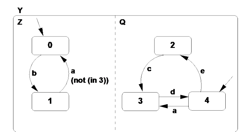
# (a) Consider the two concurrent processes represented as a Statechart in Figure 3. Give the resultant composition (product) as a single Statechart. Signals a, b, c, d, and e are inputs from the environment.
Answer
# (b) Asynchronous and synchronous composition of finite state machines.
i. List at least three differences between asynchronous and synchronous composition of two finite state machines.
ii. Describe two scenarios, where an asynchronous composition is preferable over a synchronous composition and vice-versa.
Answer
i. Differences between asynchronous and synchronous composition of two finite state machines:
Time synchrony: In synchronous composition, both finite state machines (FSMs) progress in lock-step. This means that they move from one state to the next at the same time, typically in response to a global clock signal. In asynchronous composition, however, each FSM progresses at its own pace, independently of the other.
Communication: Synchronous FSMs communicate at known intervals, typically in alignment with the global clock signal. However, asynchronous FSMs communicate based on the occurrence of certain events, and the timing of these communications can be unpredictable.
Complexity and Predictability: Synchronous composition tends to be easier to design, understand, and predict since all actions are driven by a unified clock signal. Asynchronous composition, in contrast, can be more complex to design due to the potential for race conditions, deadlocks, and other timing-related challenges.
ii. Scenarios where different types of composition are preferable:
Asynchronous composition preference: In a network routing system, various routers operate independently, forwarding packets as they arrive. The asynchronous nature of this system helps to optimize resource usage by ensuring that each router operates independently, adjusting its behavior based on the network load. The event-driven nature of packet arrival and transmission makes an asynchronous composition more suitable.
Synchronous composition preference: In a processor's pipeline, different stages (like fetch, decode, execute, and write-back) must operate in a synchronized manner. The operations in each stage are performed in lock-step with the clock signal to ensure correct operation and data consistency. In this scenario, a synchronous composition is more appropriate.
# 6. Safe State Machine, Statechart, and Mealy machine.
Questions:
# (a) Give an equivalent single (flat) Mealy machine representation for the three concurrent processes represented as a Safe State Machine (SSM) in Figure 4. A, B, and C are input signals from the environment and O is an output signal.
# (b) List at least two differences and two similarities between Statechart and Safe State Machine (SSM).
Answer
Statecharts and Safe State Machines (SSMs) are both formalisms used to model the behavior of systems. They are useful for representing complex behaviors in a graphical manner that is relatively easy to understand. Here are some differences and similarities between these two formalisms:
Differences:
Hierarchy: Statecharts support hierarchical (nested) states, which allow the representation of more complex behaviors and make the statechart more compact and easier to understand. SSMs, on the other hand, are typically flat and do not support hierarchy, which might make the representation of complex behaviors more cumbersome.
Concurrency: Statecharts support concurrent states, meaning that more than one state can be active at the same time. This is especially useful for modeling complex systems with multiple independent or interacting parts. In contrast, SSMs usually do not support concurrent states. At any given time, an SSM is typically in a single state.
Similarities:
State Transitions: Both Statecharts and SSMs utilize state transitions to represent system behavior. These transitions are triggered by certain events or conditions.
Formal Semantics: Both Statecharts and SSMs have formal semantics, meaning that the behavior they represent can be precisely defined and understood. This makes them suitable for rigorous system analysis and model checking.
Remember that these are general characterizations and specific implementations of Statecharts or SSMs might differ based on the requirements of the system or the preferences of the system designer.