# Assessment 02 - ROS based SLAM and Navigation for a Gazebo simulated robot
Thiago Lima Souto - Mat.: 19044686
Professor Dr. Khalid
Masters of Engineering - Mechatronics
Massey University - 2nd semester 2019 - Auckland
Course: 282.758 – Simulation, Modelling and Optimisation Assessment: Assessment 02 - Simulation, Modeling and OptimizationROS based SLAM and Navigation for a Gazebo simulated robot
# Assignment 02
The problem that SLAM attempts to solve is “How can a robot create a map of its surroundings and localize itself in the map it’s created by itself?” The solutions for this problem will allow a robot to navigate a terrain autonomously, without the use of external navigation sources, such as GPS.
Using appropriate sensor model (laser scanner or RGB-D camera) mounted on the robot in Gazebo (from assignment 1), you will create an optimized system that can do SLAM in a robust manner. If an obstacle or object is added to the environment of the robot, it should be able to update the map and navigate from point to point in an autonomous mode (using move_base package).
Due date:22/9/2019by 5:00PM.
Report Requirements:
- Not more than 15 pages in total including references and figures.
- Details of the robot model with screenshots and sdf snippets (particularly for the laser scanner or RGBD camera).
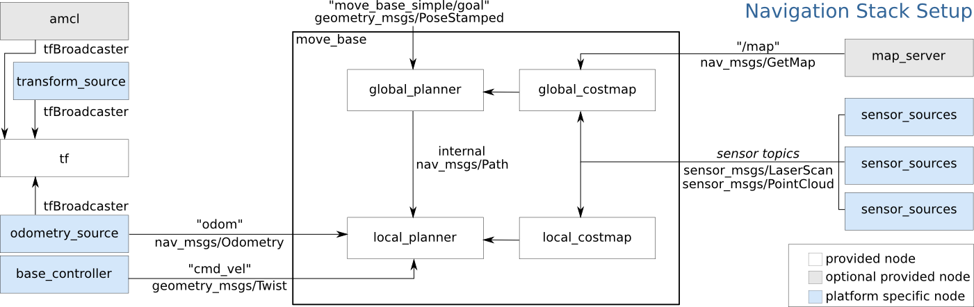
- A brief discussion on the components of navigation stack in ROS (no more than 5 pages). Append references to literature sources that describe the methods similar to those used in ROS.
- Create a ROS catkin package to move the robot using move_base and gmapping. The robot should be able to navigate to goal points provided by the user in the map (in rviz). This package can be a modified version of code taken from repositories or websites but you will need to cleanly adopt it to your needs and show your contribution clearly.
- Describe important parts of your move_basepackage (from #4).
- Create a catkin package to move the robot along goal points read from a text file.
- Submit your ROS catkin package with all necessary launch files. This code will be tested and depending on the working of your robot you will get marks for this part of the report.
# The robot model
The robot model used for this simulation was the Pionner P3DX, this robot is a differential drive movement which make the movement much simpler, you can just assume the center and rotate, unlike a car that you will be turning on a radius.
The simulation model uses many packages to perform a SLAM navigation for the Gazebo P3DX model.
The mylaunch package contain launch files that will coordinate how the robot will interact with the medium and how It's going to be configured as well as how the robot moves.
Robot configuration part of the launch files:
This part is contained in every launch file of the package. Here we are inputting some parameters for the robot and starting a gazebo world with the P#DX in it.
<launch>

	<!-- these are the arguments you can pass this launch file, for example
		paused:=true -->
	<arg name="paused" default="false" />
	<arg name="use_sim_time" default="true" />
	<arg name="gui" default="true" />
	<arg name="headless" default="false" />
	<arg name="debug" default="false" />
        <arg name="world" default="p3dx" />

	<!-- We resume the logic in empty_world.launch, changing only the name of
		the world to be launched -->
	<include file="$(find gazebo_ros)/launch/empty_world.launch">
		<arg name="world_name" value="$(find p3dx_gazebo)/worlds/$(arg world).world" />
		<arg name="debug" value="$(arg debug)" />
		<arg name="gui" value="$(arg gui)" />
		<arg name="paused" value="$(arg paused)" />
		<arg name="use_sim_time" value="$(arg use_sim_time)" />
		<arg name="headless" value="$(arg headless)" />
	</include>
2
3
4
5
6
7
8
9
10
11
12
13
14
15
16
17
18
19
20
21
Load the URDF into the ROS Parameter Server This will show up in rviz
	<param name="robot_description"
                command="$(find xacro)/xacro --inorder '$(find p3dx_description)/urdf/pioneer3dx.xacro'" />
2
Running a python script to the send a service call to gazebo_ros to spawn a URDF robot
	<node name="urdf_spawner" pkg="gazebo_ros" type="spawn_model"
                respawn="false" output="screen" args="-urdf -model p3dx -param robot_description" />
2
3
State and jointstate publishers
        <node name="joint_state_publisher" pkg="joint_state_publisher" type="joint_state_publisher" ></node>
        <node name="robot_state_publisher" pkg="robot_state_publisher" type="state_publisher" />
2
A robotic system typically has many 3D coordinate frames that change over time, such as a world frame, base frame,gripper frame, head frame, etc. tf keeps track of all these frames over time, and allows you to ask questions like:
- Where was the head frame relative to the world frame, 5 seconds ago?
- What is the pose of the object in my gripper relative to my base?
- What is the current pose of the base frame in the map frame?
tf can operate in a distributed system. This means all the information about the coordinate frames of a robot is available to all ROS components on any computer in the system. There is no central server of transform information.
A transform tree defines offsets in terms of both translation and rotation between different coordinate frames
The first thing we need to do is to create a node that will be responsible for publishing the transforms in our system. Next, we'll have to create a node to listen to the transform data published over ROS and apply it to transform a point.
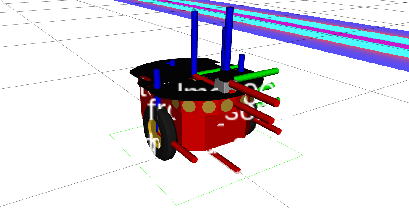
# The Laser Scanner
The Laser scanner used on the model was the Sick LMS100 laser range finder. It has one Published Topic "scan", which is normally remapped for the topic used on the model, in our case we remapped the scan to /laser/scan topic. The type of message that It publishes is the sensor_msgs/LaserScan.msg and is defined as below:
std_msgs/Header header
float32 angle_min
float32 angle_max
float32 angle_increment
float32 time_increment
float32 scan_time
float32 range_min
float32 range_max
float32[] ranges
float32[] intensities
2
3
4
5
6
7
8
9
10
There are 2 parameters on this laser to be configured, the host and the frame_id.
Below is a Figure with the Robot model using the laser inside the Gazebo environment:
The other packages of the model will be described ahead when the navigation stack in ROS will be discussed, they are:
- geometry 2
- navigation
- navigation_msgs
- pioneer_p3dx_model
- openslam_gmapping
- slam_gmapping
- teleop_twist_keyboard
- simple_navigation_goals
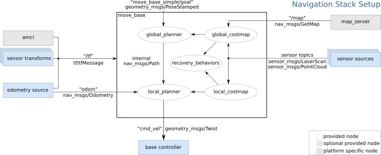
# Navigation Stack
# Creating a package
The mylaunch package will store all the configuration and launch files for the navigation stack.
This package will have dependencies on any packages used to fulfill the requirements in the Robot Setup as well as on the move_base package.
On catkin_ws/src create the package.
# Costmap Configuration (local_costmap) & (global_costmap)
The global costmap creates long-term plans across the whole environment, and the local costmap is used for local planning and avoidance of obstacles.
The costmap 2d package provides a configurable structure that keeps information on where the robot should navigate as an occupancy grid. The costmap uses sensor data and static map information to store and update worldwide barrier information through the object costmap 2d::Costmap2DROS.
Costmap 2d::Costmap2DROS is the main interface that maintains much of the functionality related to ROS. It includes a costmap 2d::LayeredCostmap used to track each layer.
Using pluginlib, each layer is installed in the Costmap2DROS and added to the LayeredCostmap.
The layers themselves can be individually compiled, allowing arbitrary costmap changes to be made via the C++ interface. The costmap 2d::Costmap2D class implements the basic data structure for the two-dimensional costmap storage and access.
# Marking and Clearing
The costmap subscribes to sensor topics over ROS automatically and updates itself accordingly. Each sensor is either used to mark (insert information about obstacles in the costmap), to clear (remove information about obstacles from the costmap), or both.
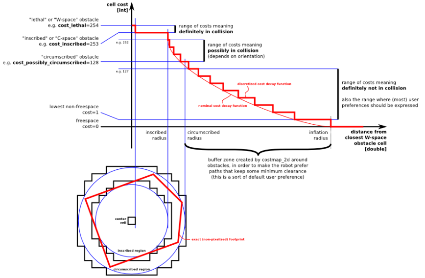
# Occupied, Free, and Unknown Space
Each cell may be free, occupied, or unknown in this structure. Each status is assigned a special cost value when projected into the cost map.
Columns with a certain number of occupied cells are assigned a costmap 2d::LETHALOBSTACLE cost, columns with a certain number of unknown cells, according to the unknown threshold parameter, costmap 2d::NO INFORMATION cost is assigned, and other columns costmap 2d::FREESPACE cost is assigned.
# Map Updates
The costmap performs cycles of map updates at the rate specified by the parameter update frequency. Each cycle, sensor data is entered, marking and clearing operations are carried out in the costmap's underlying occupancy structure, and this structure is projected into the costmap where appropriate cost values are assigned.
After this, each obstacle inflation is performed on each cell with a costmap_2d::LETHAL_OBSTACLE cost.
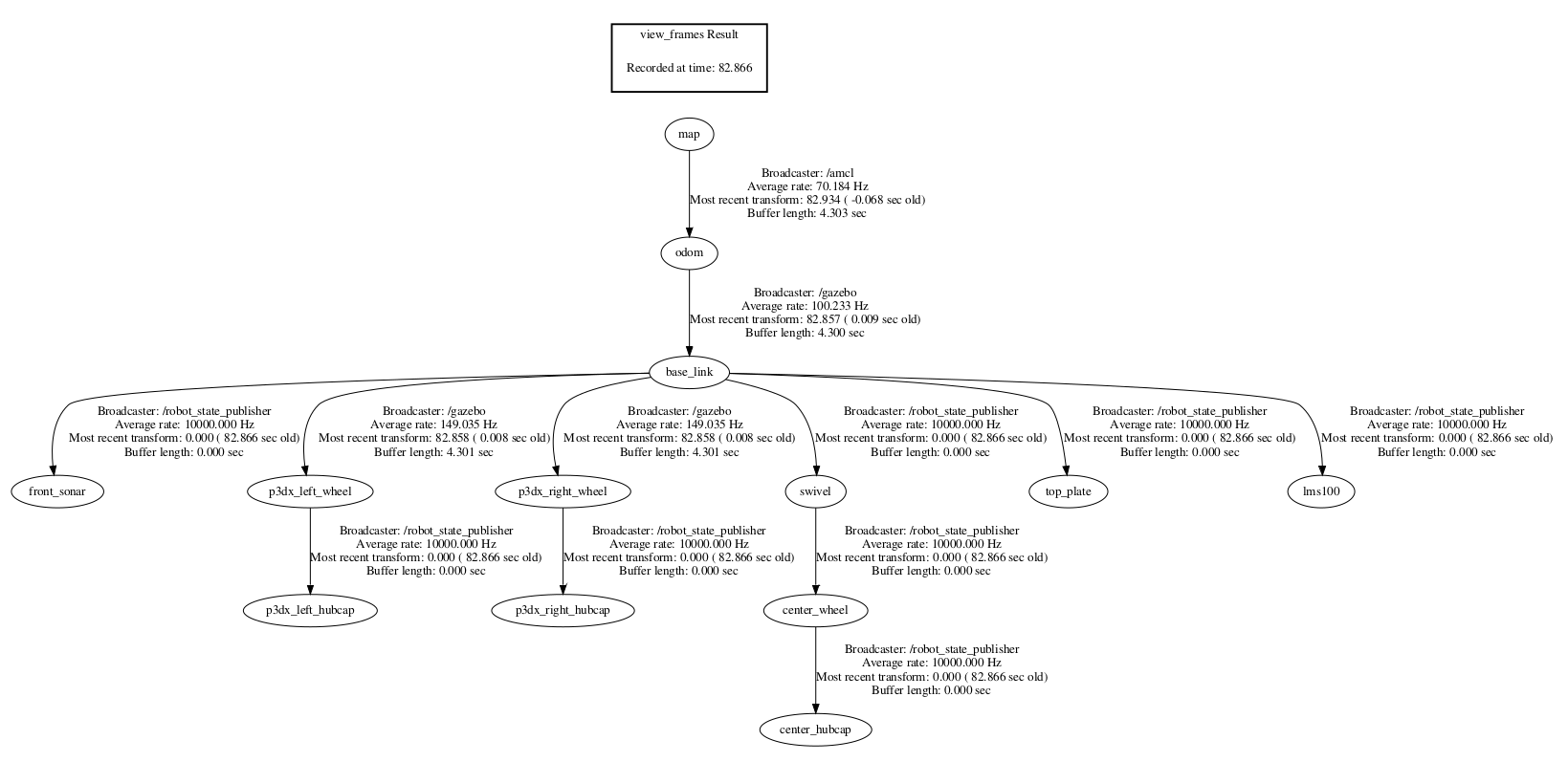
# tf
The costmap 2d::Costmap2DROS object makes extensive use of tf to insert data from sensor sources into the costmap.
The parameter transform tolerance sets the maximum permitted latency between these transforms. If the tf tree is not updated at the expected rate, the robot is stopped by the navigation stack.
# Inflation
Inflation is the process of propagating cost values that decrease with distance from occupied cells.
# Map Types
There are two main ways to initialize a costmap_2d::Costmap2DROS object. The method we are going to use is to seed it with a user-generated static map (see the map_server package for documentation on building a map). In this case, the costmap is initialized to match the width, height, and obstacle information provided by the static map. This configuration is normally used in conjunction with a localization system, like amcl, that allows the robot to register obstacles in the map frame and update its costmap from sensor data as it drives through its environment.
# amcl
Amcl is a probabilistic 2D robot location system. It implements the Monte Carlo localization, adaptive (or KLD-sampling) approach, which uses a particle filter to track a robot's pose against a known map.
As currently implemented, this node works only with laser scans and laser maps. It could be extended to work with other sensor data.
# SLAM
# Overview
Simultaneous Localization And Mapping
This is the overview of the Navigation Project, We will break It down in small pieces and implement them to achieve the overall goal
# slam_gmapping
Slam gmapping asks for the openslam_gmapping
rosrun gmapping slam_gmapping scan:=/laser/scan were use to remap the default scan topic to the /laser/scan
The slam_gmapping node takes in sensor_msgs/LaserScan messages and builds a map (nav_msgs/OccupancyGrid). The map can be retrieved via a ROS topic or service.
<node pkg="gmapping" name="slam_gmapping" type="slam_gmapping" output="screen"/>
# Serving the map
Two maps were used for this project Willow garage and a custom map made by moving the robot around and recording a .bag file which was then played to create the map to be served to the map_server.
<node name="map_server" pkg="map_server" type="map_server" args="$(find p3dx_gazebo)/maps/wgmap.yaml" output="screen"/>
2
or
<node name="map_server" pkg="map_server" type="map_server" args="$(find p3dx_gazebo)/maps/mylaserdata.yaml" output="screen"/>
2
# rviz
<arg name="model" default="$(find p3dx_description)/urdf/pioneer3dx.urdf"/>
<!--arg name="gui" default="False" /-->
<param name="robot_description" textfile="$(arg model)" />
<param name="use_gui" value="$(arg gui)"/>
<!--node name="joint_state_publisher" pkg="joint_state_publisher" type="joint_state_publisher" ></node-->
<!--node name="robot_state_publisher" pkg="robot_state_publisher" type="state_publisher" /-->
<node name="rviz" pkg="rviz" type="rviz" args="-d $(find p3dx_description)/launch/myconfig.rviz" />
2
3
4
5
6
7
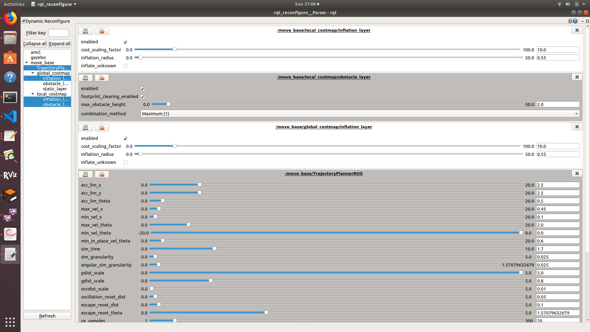
# To configure the parameters of the move_base:
A very useful tools were used to configure the parameters of the move_base node.
rosrun rqt_reconfigure rqt_reconfigure
# Sending simple goals
On the implementation of this model sending simple goals to move the robot was the approach used. This is the cpp file of this implementation
#include <ros/ros.h>
#include <move_base_msgs/MoveBaseAction.h>
#include <actionlib/client/simple_action_client.h>

typedef actionlib::SimpleActionClient<move_base_msgs::MoveBaseAction> MoveBaseClient;

int main(int argc, char** argv){
  ros::init(argc, argv, "simple_navigation_goals");

  //tell the action client that we want to spin a thread by default
  MoveBaseClient ac("move_base", true);

  //wait for the action server to come up
  while(!ac.waitForServer(ros::Duration(5.0))){
    ROS_INFO("Waiting for the move_base action server to come up");
  }

  move_base_msgs::MoveBaseGoal goal;

  //we'll send a goal to the robot to move 1 meter forward
  goal.target_pose.header.frame_id = "base_link";
  goal.target_pose.header.stamp = ros::Time::now();

  goal.target_pose.pose.position.x = 1.0;
  goal.target_pose.pose.orientation.w = 1.0;

  ROS_INFO("Sending goal");
  ac.sendGoal(goal);

  ac.waitForResult();

  if(ac.getState() == actionlib::SimpleClientGoalState::SUCCEEDED)
    ROS_INFO("Hooray, the base moved 1 meter forward");
  else
    ROS_INFO("The base failed to move forward 1 meter for some reason");

  return 0;
}
2
3
4
5
6
7
8
9
10
11
12
13
14
15
16
17
18
19
20
21
22
23
24
25
26
27
28
29
30
31
32
33
34
35
36
37
38
We also have to include on the makefile the executable references so the file can be launched later.
src/simple_navigation_goals.cpp file to our CMakeLists.txt:
add_executable(simple_navigation_goals src/simple_navigation_goals.cpp)
target_link_libraries(simple_navigation_goals ${catkin_LIBRARIES})
2
# The structure of the simulation
# Topics
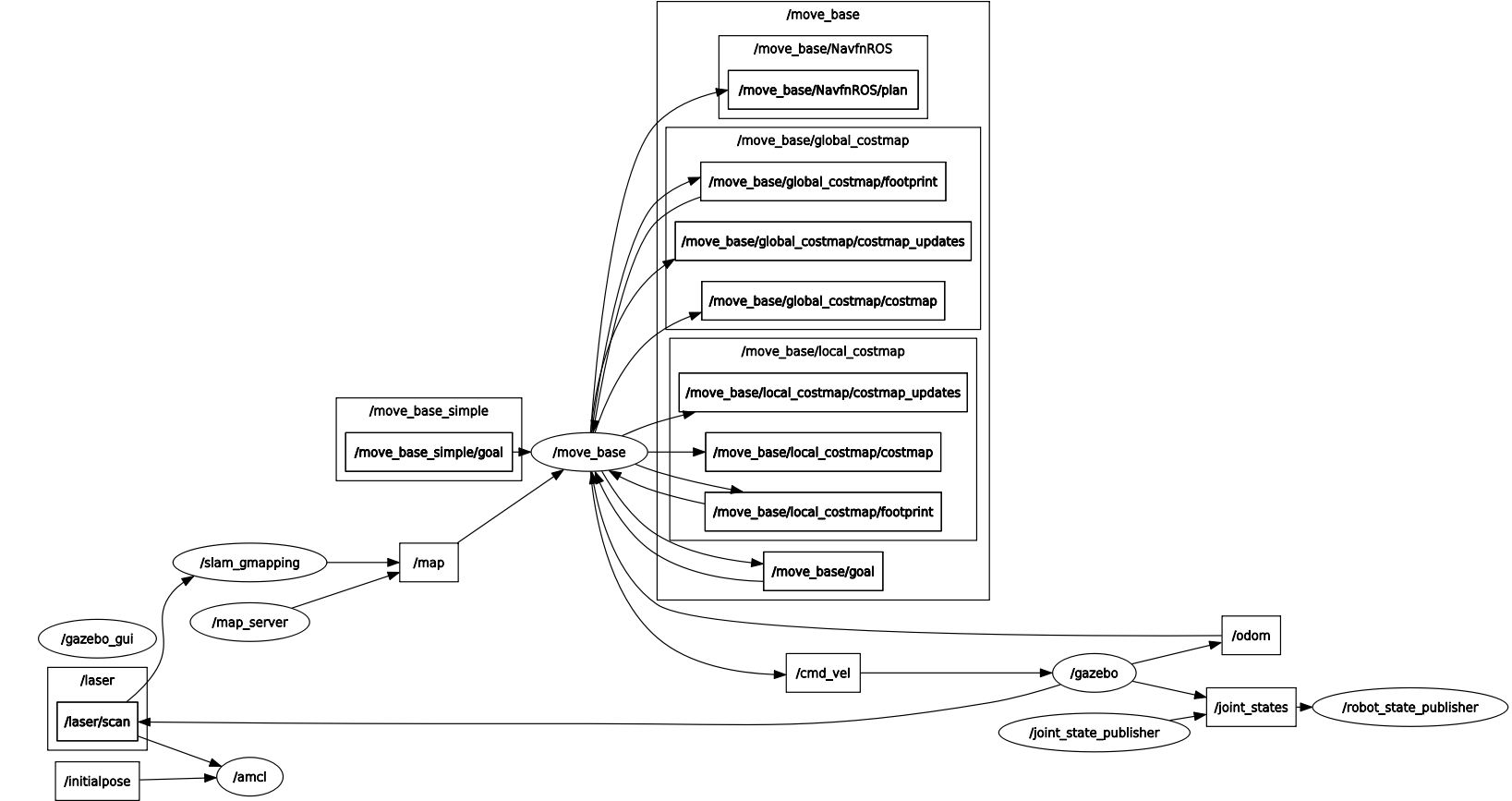
# Nodes
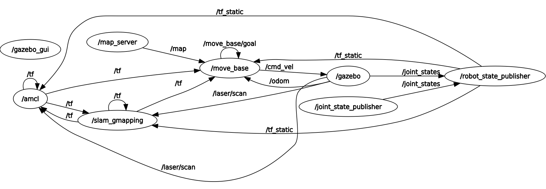
# Frames
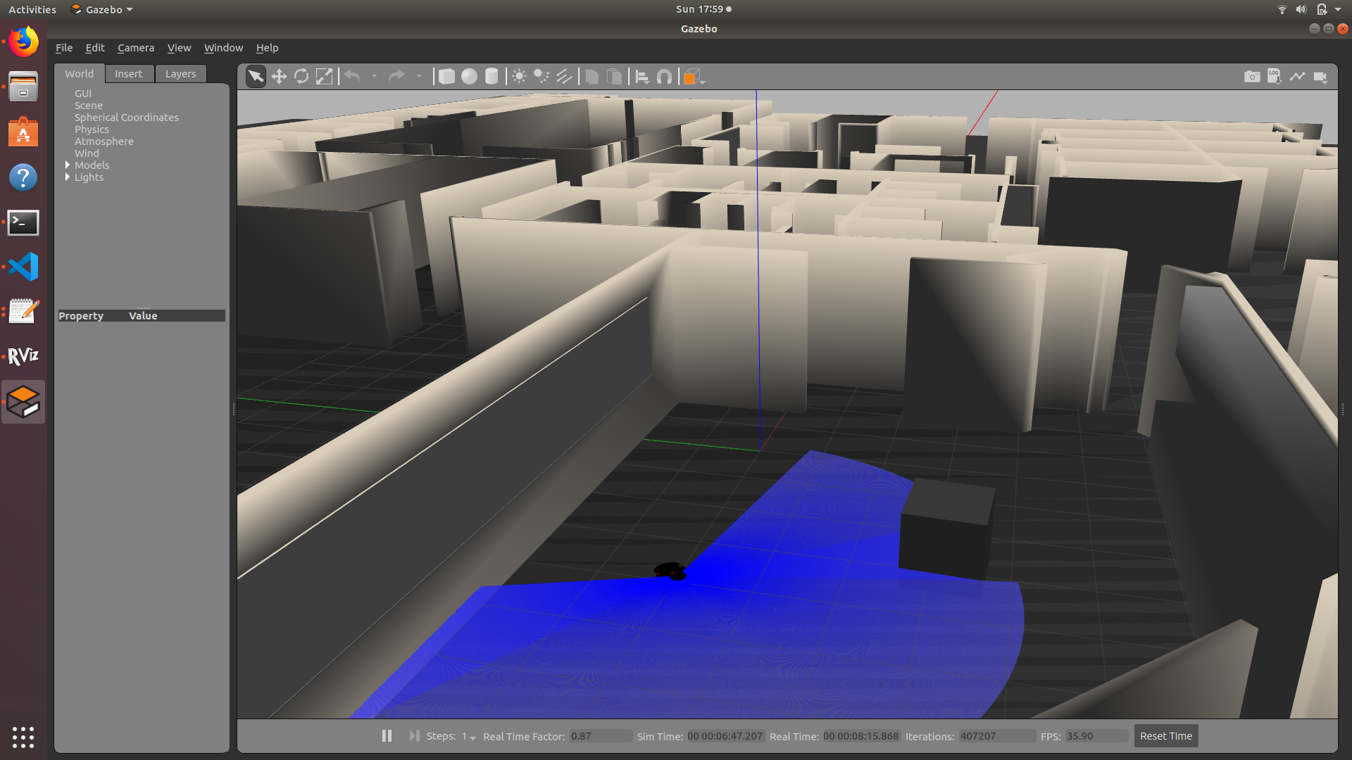
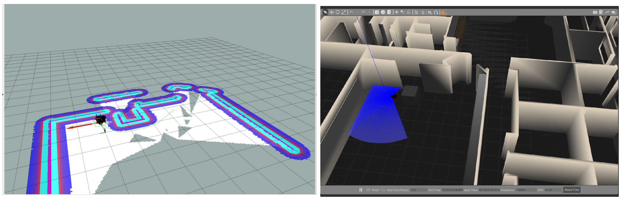
# Examples of path perfor
Inside rviz and gazebo avoiding a box as obtacle:
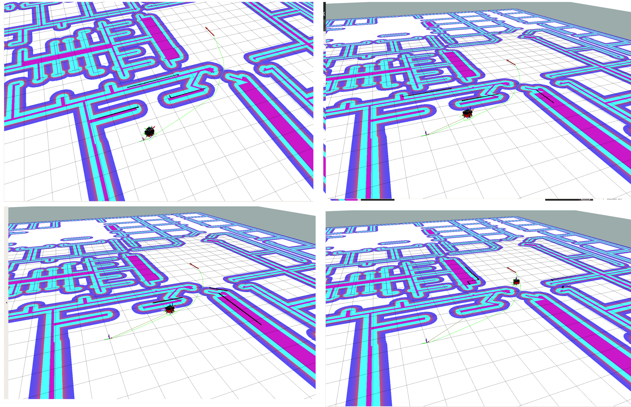
Inside the willow garage map going for a goal:
# References
http://docs.ros.org
http://wiki.ros.org