# Final Project
# Resources
DETAILS
# Research papers
# Courses to be taken
# Research
Omni-Crawler Drives In All Directions #DigInfo
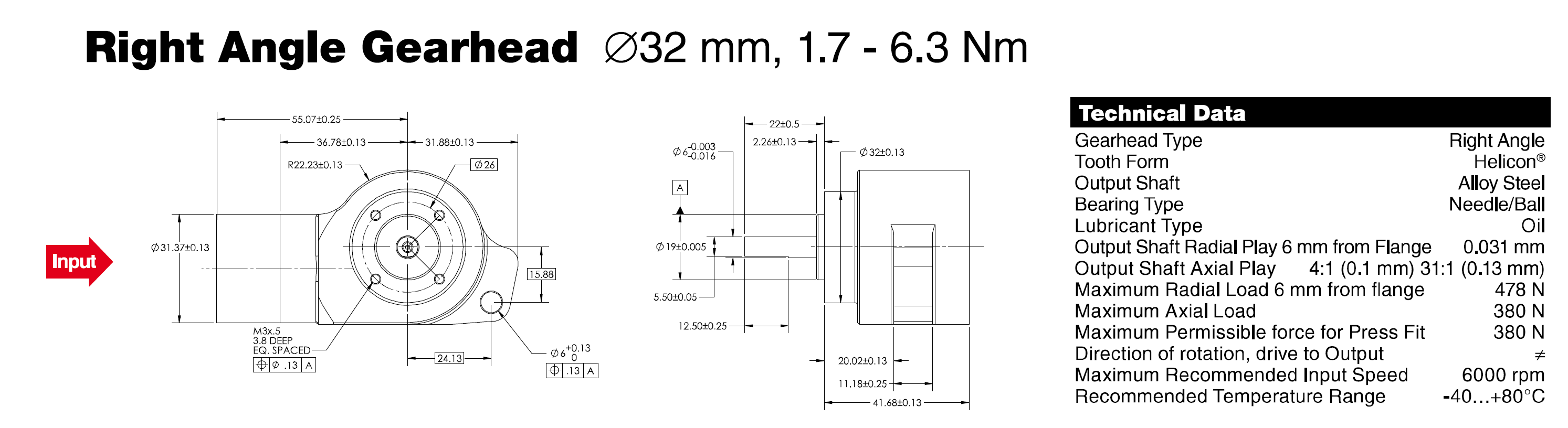
Spiro right angle maxon Gearbox
# Jetson and OpenCV
# TensorRT
# Rope Access weld acanning
# Gears
# OpenCV Structured light
Structured light API - Examples
# TensorRT and Mask RCNNs in jetson Nano Repository
Github TensorRT Jetson Nanno Mask RCNN
# Design Paradigms
| Paradigms | Pros | Cons |
|---|---|---|
| Detachable Wheels? |
|
|
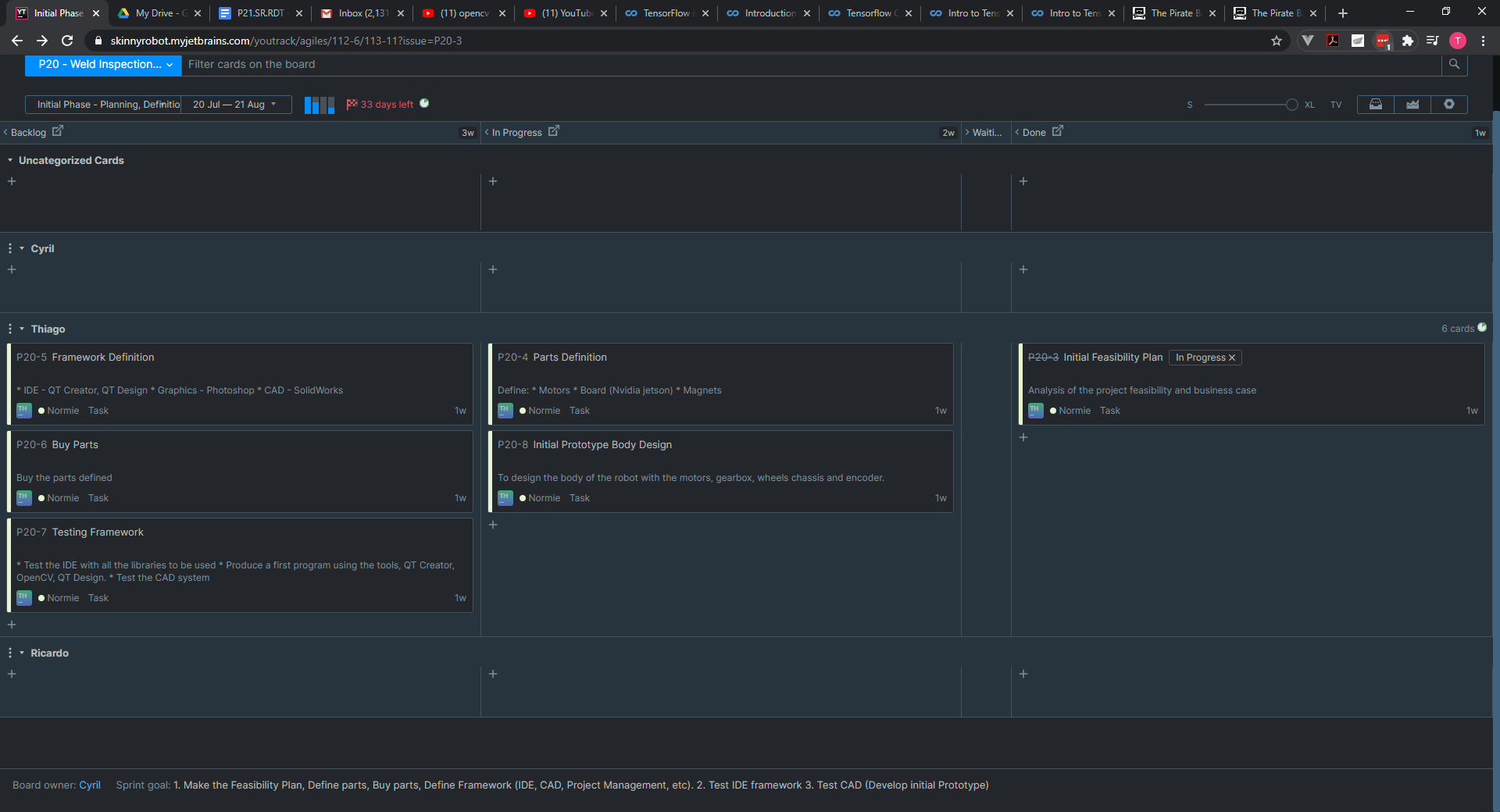
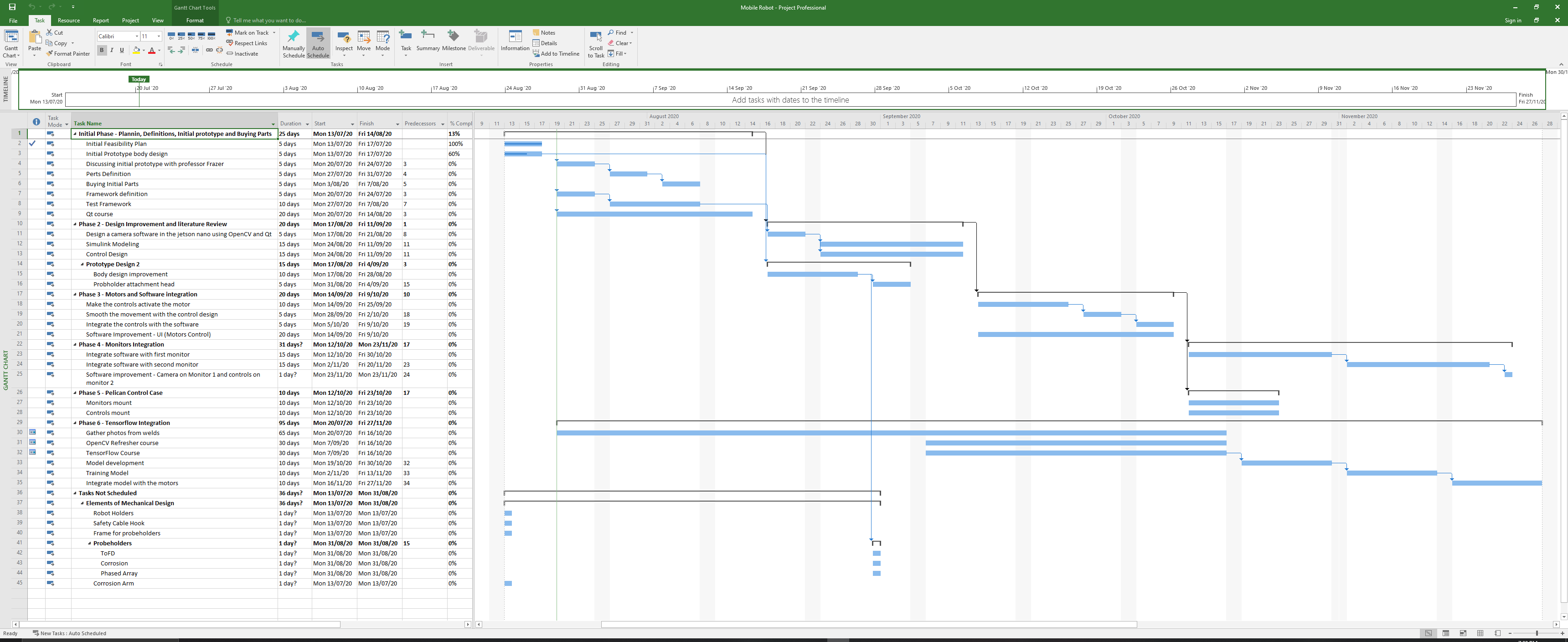
# Project Management
Project Update at 01/08/2020
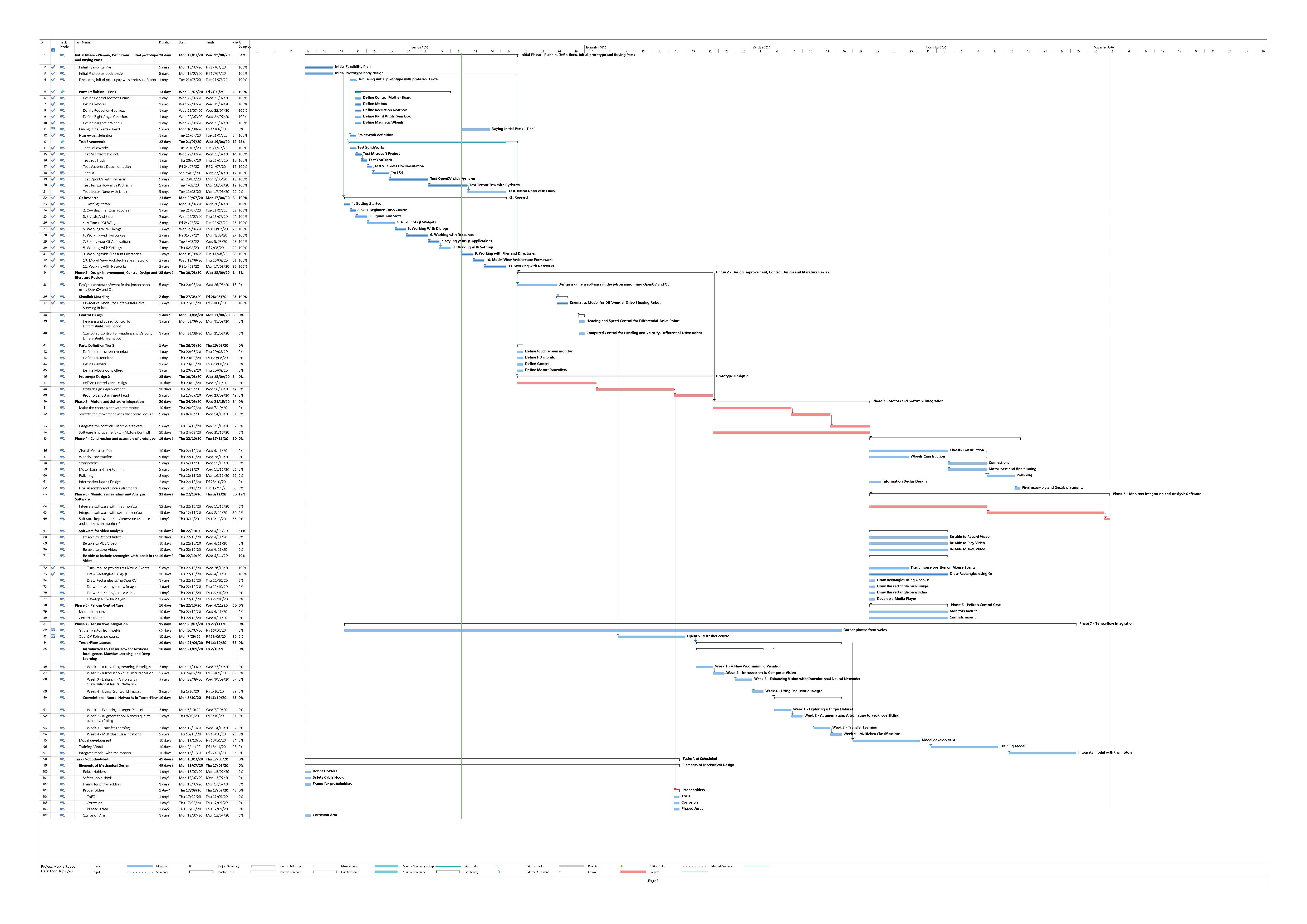
# Phase 1 - Initial Phase - Planning, Definitions, Initial prototype and Buying Parts
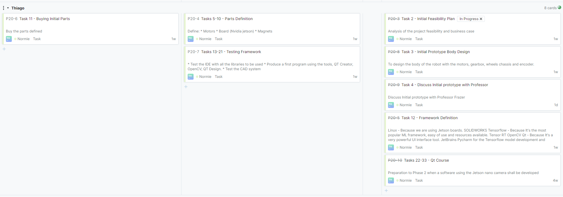
# Task 02 - Initial Feasibility Plan ✅
This plan is taking in consideration a company and commercial perspective as well as the social impact.
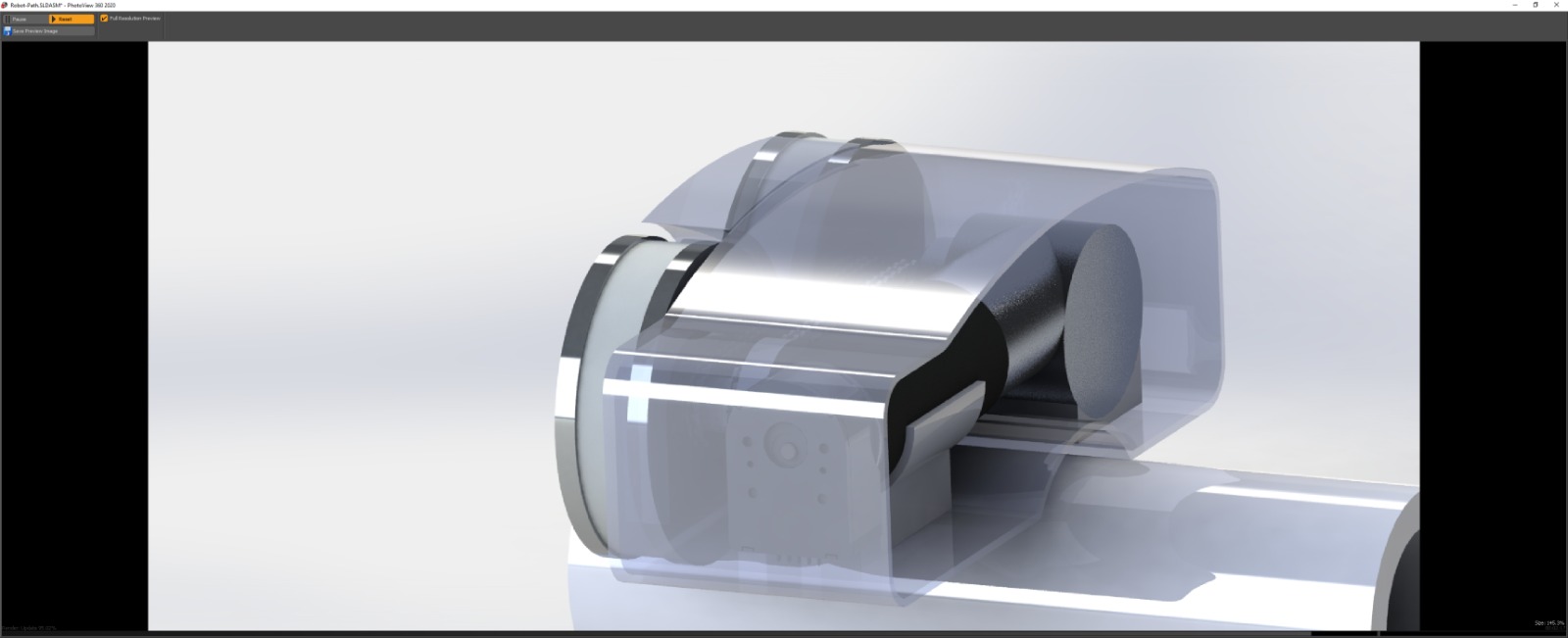
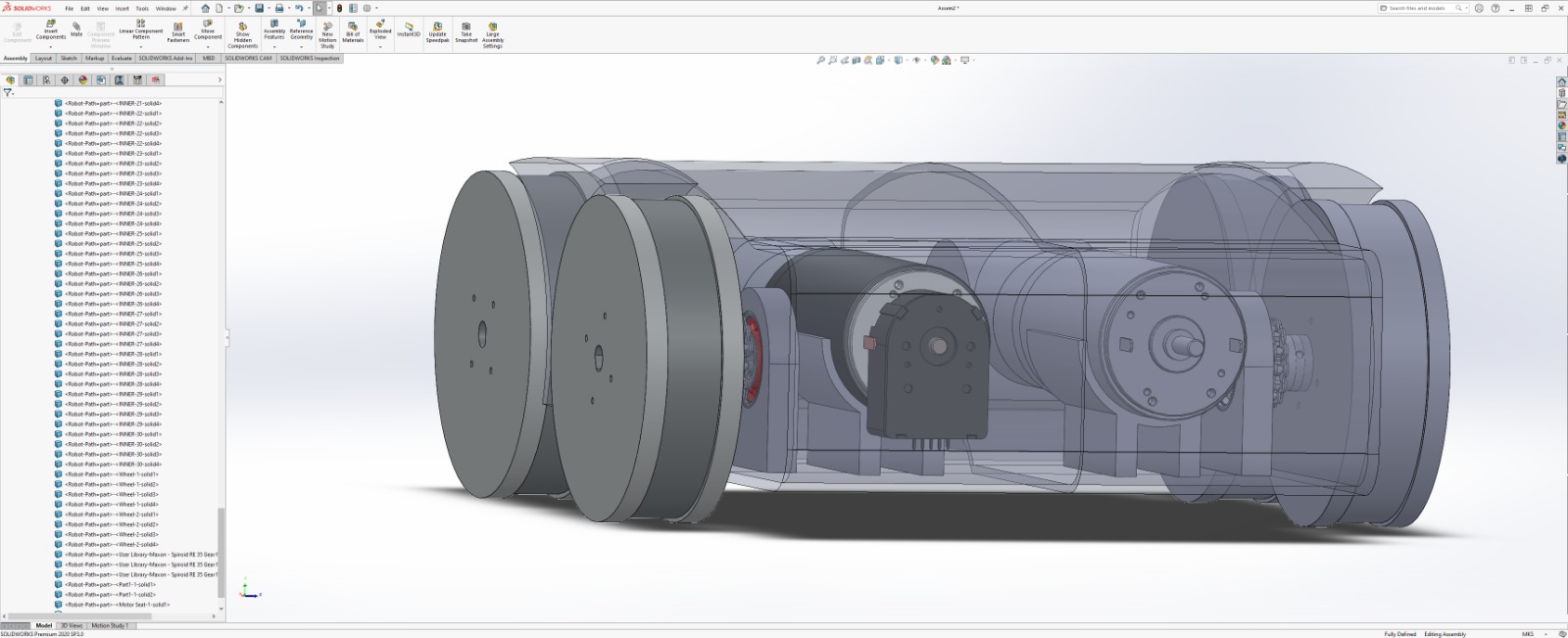
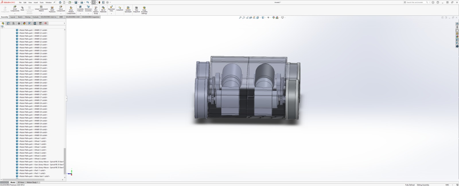
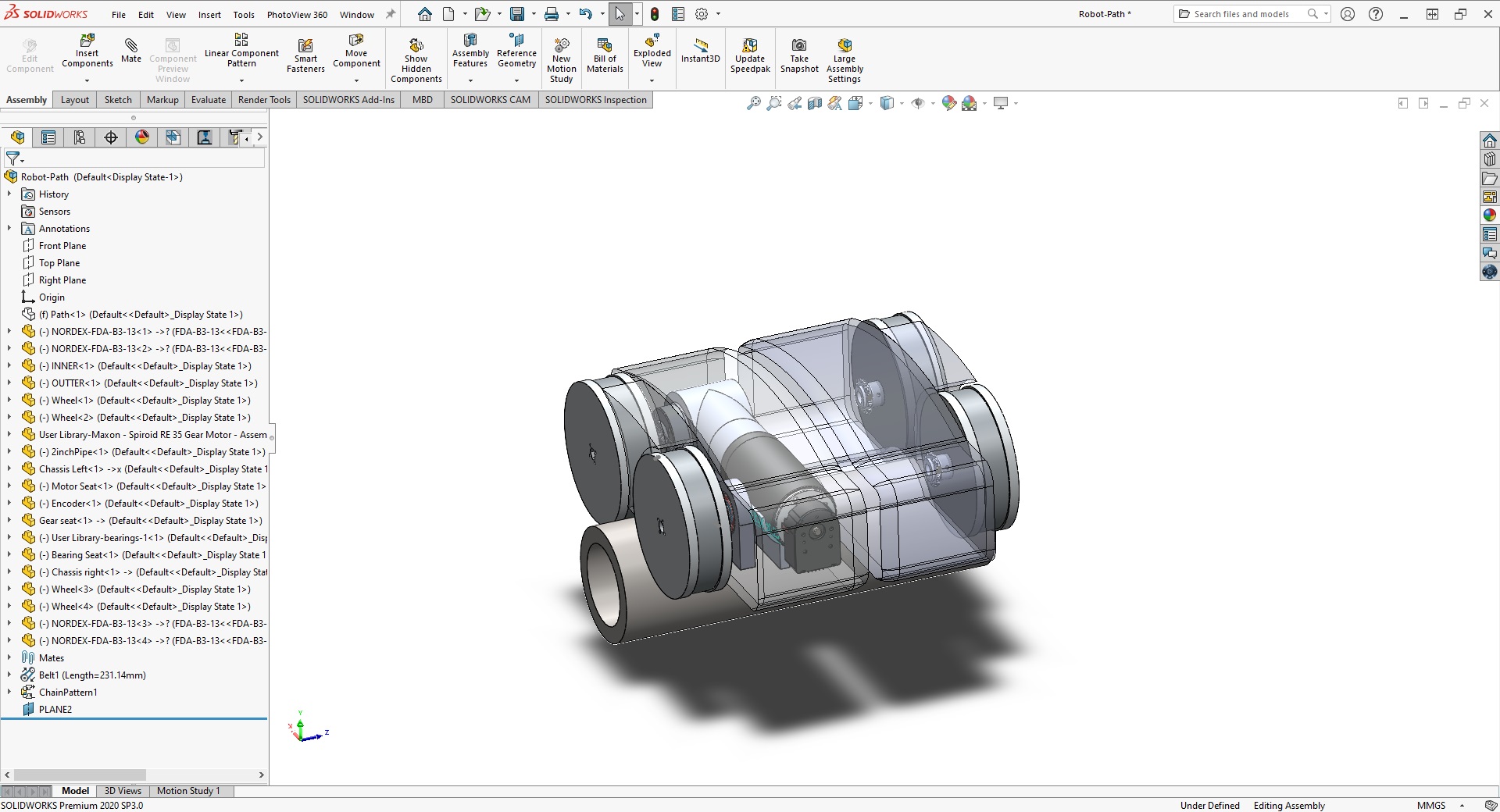
# Task 03 - Initial Prototype Design ✅
The initial prototype made in Solidworks has included:
- Magnetic Wheels
- Motors
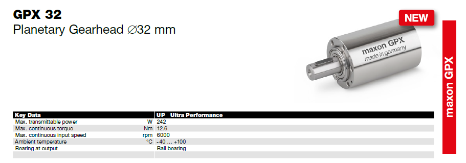
- Gearbox
- 90 gearbox - Spirol Gear Maxon
- Sprockets
- Chain
- Chassis
# Task 04 - Discussing initial Prototype with professor Frazer ✅
Tuesday after class 21/07/2020
Done.
From the discussion:
- The Plan is OK but tight.
- Parts defined (Motor and gears from Maxon, as well as controller).
- Tensor RT Added to the framework to gain speed on the image processing.
- Questions about the programming language and operational system solved (C++, Python and Ubuntu).
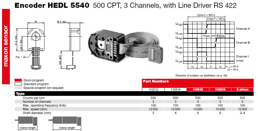
- Maybe consider 2 encoders, to compensate position by comparison.
- Research about belts instead of chain, although the chain is good already.
# Tasks 05-10 - Parts definition
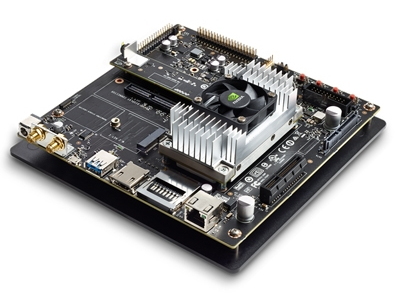
# 1. Control Mother Board
Jetson TX2
# 2. Motors
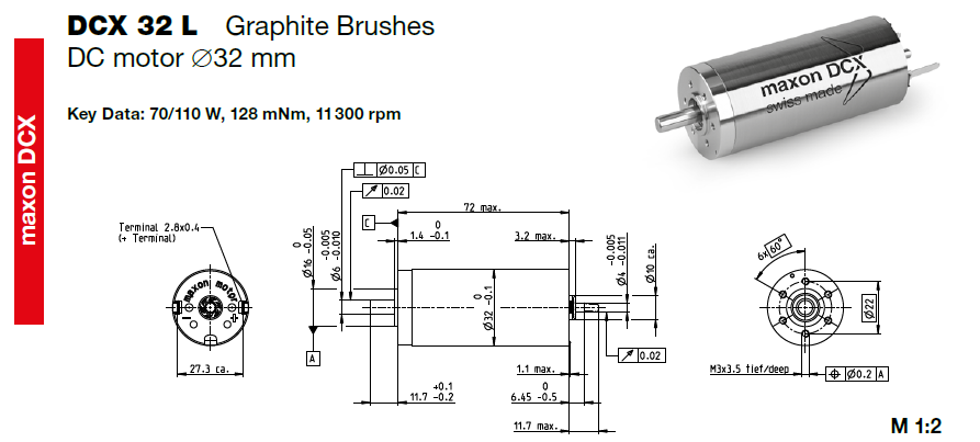
# 3. Reduction Gearbox
# 4. Right Angle Gear Box
# 5. Motor Controllers
WARNING
To be defined
# 6. Encoders
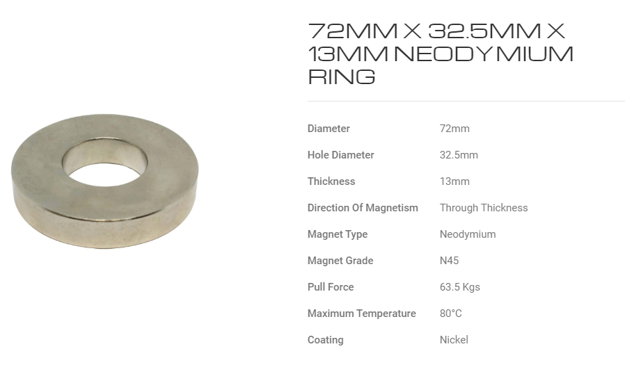
# 7. Magnetic Wheels
WARNING
In house designed wheels using the magnet below:
# 8. Touch Screen Monitor
WARNING
To be defined
# 9. HD monitor
WARNING
To be defined
# 10. Camera
WARNING
To be defined
# Task 11 - Buying Initial Parts
Funds available on beginning of August (10/08/2020)
# Task 12 - Framework Definition ✅
| IDE's | Operational System | Software | Technology |
|---|---|---|---|
| JetBrains Pycharm JetBrains Youtrack JetBrains WebStorm Qt | Linux (Hardware) Windows (PM and Documentation) | Solidworks (CAD) Microsoft Project (PM) Jetbrains YouTrack (Agile PM) | TensorFlow (Machine Learning) Tensor TR (Machine Learning booster) OpenCV (Computer Vision) |
# Defined tools
- Linux - Because we are using Jetson boards.
- SOLIDWORKS
- Tensorflow - Because It's the most popular ML framework, easy of use and resources available.
- Tensor RT
- OpenCV
- Qt - Because It's a very powerful UI interface tool.
- JetBrains Pycharm for the Tensorflow model development and training in Python.
- JetBrains Youtrack - Agile Project Management
- Microsoft Project - Planning and Tracking
- Vuepress - Documentation - JetBrains WebStorm
- Microsoft Project for planning
# Questions about the framework
# C++ or Python?
| C++ | Python |
|---|---|
| Speed | Lower Speed |
| Less resources to learn | Plenty of resources |
| QT creator uses C++ | Have to use PyQT |
Question: Is Python better for prototyping the application then, after the application is defined, convert into C++? Or is it worth to make the application directly on C++?
# Answer
C++ for controlling and UI and Python for development and training model.
# Qt creator or Clion?
| Qt | CLion |
|---|---|
| User interface components available as tools | Need to use code for visual all the time |
| OpenCV is easier to use on Windows | No problems using OpenCV in Linux which will be the platform of choice |
| USD 500.00 Year license | USD 200.00 Year License (USD 649.00 for all Jetbrains, including WebStorm and Pycharm) |
# Answer
Qt for the complete tool set for UI and Pycharm for the tensorflow development. Later on the model generated in python will be consumed by the C++ program.
# Linux Embedded?
Ubuntu can start without the ubuntu interface and directly into the software. Although some good aspects like accessing a browser from the pelican case or editing a report has to be taken into consideration.
WARNING
Consider this aspect later on
# Tasks 13-21 - Test Framework
WARNING
50%
# Task 21 - Test Jetson Nano with Linux
Install QT Install OpenCV Execute the .sh file.
Here is the video if a version 3.x is needed
Pre installed libraries on Jetson nano:
Python, OpenCV, TensorFlow/Keras and TensorRT
WARNING
# Tasks 22-33 - Qt course ✅
Finished, although possibility to expand to a new course in Qt Due to early finishing the task. Or maybe some literature review.
TIP
End of Phase 1 ⛳️
# Phase 2 - Design Improvement, Control Design and literature Review - Starting at 20/08/2020 - Tasks 34-49
# Task 37 - Kinematics Model for Differential-Drive Steering Robot
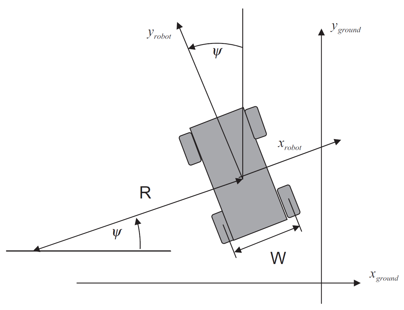
Let represent the instantaneous radius of curvature of the robot trajectory. The width of the vehicle, i.e., spacing between the wheels, is designated as . From geometrical considerations we have:
and
Now subtracting the two above equations yields
so we obtain for the angular rate of the robot
Solving for the instantaneous radius of curvature, we have:
or finally
This results in the expression for velocity along the robot’ s longitudinal axis:
In summary, the equations of motion in robot coordinates are:
and
If we convert to earth coordinates these become:
and
We may wish to account for the fact that velocities cannot change instantaneously. Thus, we would introduce as the control variables the velocity rates:
and
The system of equations for this kinematic model is now fifth order. We can use the Euler integration method for obtaining a discrete-time model for this system of nonlinear equations,
Discrete-time model for this system of nonlinear equations
and
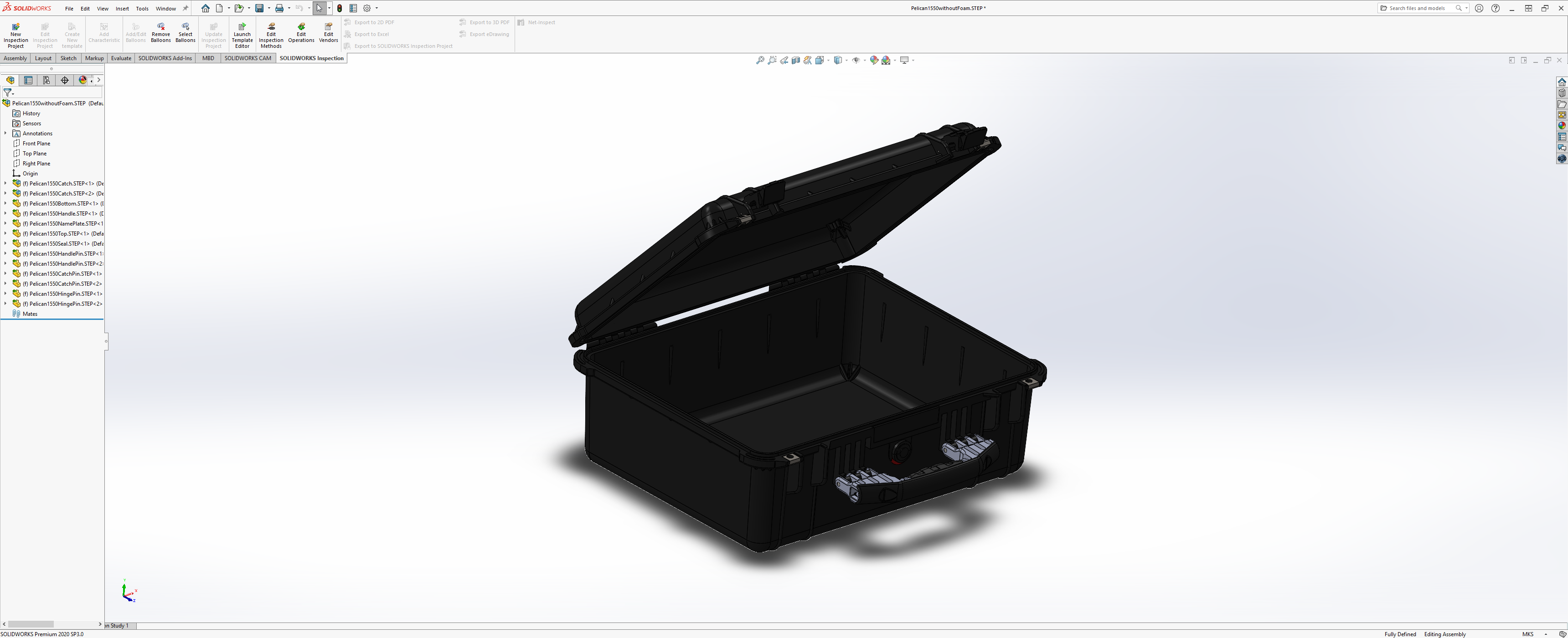
# Task 47 - Pelican Control Case Design
# Phase 5 - Monitors integration and Analysis Software - Tasks 63-73
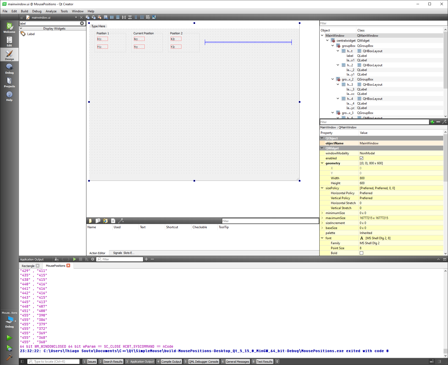
# Task 72-73 - Track mouse position on Mouse Events
- QWidget::mousePressEvent(), QWidget::mouseReleaseEvent() and QWidget::mouseMoveEvent()
To react to mouse events like press, release and move we can use the QWidget class.
widget.h
#ifndef WIDGET_H
#define WIDGET_H

#include <QWidget>
#include <QPoint>
#include <QMouseEvent>
#include <QDebug>
#include <QPainter>

QT_BEGIN_NAMESPACE
namespace Ui { class Widget; }
QT_END_NAMESPACE

class Widget : public QWidget
{
    Q_OBJECT

signals:
    void mousePressed(const QPoint&);
    void mouseReleased(const QPoint&);
    void mouseMoved(const QPoint&);

public:
    Widget(QWidget *parent = nullptr);
    ~Widget();

    void mousePressEvent(QMouseEvent* event);
    void mouseReleaseEvent(QMouseEvent *event);
    void mouseMoveEvent(QMouseEvent *event);

    QString x1;
    QString y1;
    QString xc;
    QString yc;
    QString x2;
    QString y2;

public slots:

    void paintEvent(QPaintEvent *event);

private:
    Ui::Widget *ui;
};
#endif // WIDGET_H
2
3
4
5
6
7
8
9
10
11
12
13
14
15
16
17
18
19
20
21
22
23
24
25
26
27
28
29
30
31
32
33
34
35
36
37
38
39
40
41
42
43
44
45
widget.cpp
#include "widget.h"
#include "./ui_widget.h"

Widget::Widget(QWidget *parent)
    : QWidget(parent)
    , ui(new Ui::Widget)
{
    ui->setupUi(this);
}

Widget::~Widget()
{
    delete ui;
}

void Widget::mousePressEvent(QMouseEvent *event)
{
    const QPoint p = event->pos();
    emit mousePressed(p);
    x1 = QString::number(event->x());
    y1 = QString::number(event->y());
    qDebug() << x1 << "," << y1;
    ui->label_x1->setText(x1);
    ui->label_y1->setText(y1);
}

void Widget::mouseReleaseEvent(QMouseEvent *event)
{
    const QPoint p = event->pos();
    emit mouseReleased(p);
    xc = QString::number(event->x());
    yc = QString::number(event->y());
    qDebug() << xc << "," << yc;
    ui->label_x2->setText(xc);
    ui->label_y2->setText(yc);
}

void Widget::mouseMoveEvent(QMouseEvent *event)
{
    const QPoint p = event->pos();
    emit mouseMoved(p);
    x2 = QString::number(event->x());
    y2 = QString::number(event->y());
    qDebug() << x2 << "," << y2;
    ui->label_xc->setText(x2);
    ui->label_yc->setText(y2);
}

void Widget::paintEvent(QPaintEvent *event)
{
    QPainter painter(this);
    QPen pen;
    pen.setColor(Qt::green);
    pen.setWidth(5);

    painter.setPen(pen);

    painter.drawRect(QRect(x1.toInt(), y1.toInt(), (x2.toInt()-x1.toInt()), (y2.toInt()-y1.toInt())));
    qDebug() << "box";
    update();
}
2
3
4
5
6
7
8
9
10
11
12
13
14
15
16
17
18
19
20
21
22
23
24
25
26
27
28
29
30
31
32
33
34
35
36
37
38
39
40
41
42
43
44
45
46
47
48
49
50
51
52
53
54
55
56
57
58
59
60
61

Investigate
QWidget had to be used instead of a QMainWindow, which was not being updated by the Qpainter SLOT.
How to link the widget inside the QMainWindow.
Next steps get the initial, current and release position and draw a rectangle to identify features in the video.
Obs.: This is an extra capability and is not required for the project. The reason for implementation is that during the studies of Qt I have come across this capability and decided to record while I was studying.
Maybe using QPainter to make the rectangles?

Video Player with OpenCV and Qt
https://github.com/shashwatjain8/MediaPlayer
WARNING
Consider Optical filter for red light