# TwinCAT
# Boolean logic
# Python
# %%

# notebook for generating logic tables
# https://en.wikipedia.org/wiki/Boolean_algebra

# Boolean AND

A = [False, True]
B = [False, True]

print("Boolean AND")

for a in A:
    for b in B:
        c = a and b
        print("{} AND {} = {}".format(a, b, c))

print()

A = [0b0, 0b1]
B = [0b0, 0b1]

print("Bitwise AND")

for a in A:
    for b in B:
        c = a & b
        print("{} & {} = {}".format(a, b, c))

print()

A = 0b1100
B = 0b1001

C = A & B

print("Bitwise example:")
print("  {:08b}\n& {:08b}\n  {:08b}".format(A, B, C))
2
3
4
5
6
7
8
9
10
11
12
13
14
15
16
17
18
19
20
21
22
23
24
25
26
27
28
29
30
31
32
33
34
35
36
37
38
Boolean AND

False AND False = False
False AND True = False
True AND False = False
True AND True = True

Bitwise AND

0 & 0 = 0
0 & 1 = 0
1 & 0 = 0
1 & 1 = 1

Bitwise example:

  00001100
& 00001001
  00001000
2
3
4
5
6
7
8
9
10
11
12
13
14
15
16
17
18
19
# %%

# Boolean OR

A = [False, True]
B = [False, True]

print("Boolean OR")

for a in A:
    for b in B:
        c = a or b
        print("{} OR {} = {}".format(a, b, c))

print()

A = [0b0, 0b1]
B = [0b0, 0b1]

print("Bitwise OR")

for a in A:
    for b in B:
        c = a | b
        print("{} | {} = {}".format(a, b, c))

print()

A = 0b1100
B = 0b1001

C = A | B

print("Bitwise example:")
print("  {:08b}\n| {:08b}\n  {:08b}".format(A, B, C))
2
3
4
5
6
7
8
9
10
11
12
13
14
15
16
17
18
19
20
21
22
23
24
25
26
27
28
29
30
31
32
33
34
35
Boolean OR

False OR False = False
False OR True = True
True OR False = True
True OR True = True

Bitwise OR

0 | 0 = 0
0 | 1 = 1
1 | 0 = 1
1 | 1 = 1

Bitwise example:

  00001100
| 00001001
  00001101
2
3
4
5
6
7
8
9
10
11
12
13
14
15
16
17
18
19
#%%

# Boolean XOR

A = [False, True]
B = [False, True]

print("Boolean XOR")

for a in A:
    for b in B:
        c = (a != b)
        print("{} XOR {} = {}".format(a, b, c))

print()

A = [0b0, 0b1]
B = [0b0, 0b1]

print("Bitwise XOR")

for a in A:
    for b in B:
        c = a ^ b
        print("{} ^ {} = {}".format(a, b, c))

print()

A = 0b1100
B = 0b1001

C = A ^ B

print("Bitwise example:")
print("  {:08b}\n^ {:08b}\n  {:08b}".format(A, B, C))
2
3
4
5
6
7
8
9
10
11
12
13
14
15
16
17
18
19
20
21
22
23
24
25
26
27
28
29
30
31
32
33
34
35
Boolean XOR

False XOR False = False
False XOR True = True
True XOR False = True
True XOR True = False

Bitwise XOR

0 ^ 0 = 0
0 ^ 1 = 1
1 ^ 0 = 1
1 ^ 1 = 0

Bitwise example:

  00001100
^ 00001001
  00000101
2
3
4
5
6
7
8
9
10
11
12
13
14
15
16
17
18
19
20
# %%

# Boolean NOT

A = [False, True]

print("Boolean NOT")
for a in A:
    b = not a
    print("NOT {} = {}".format(a, b))

print()

A = [0b0, 0b1]

print("Bitwise NOT via XOR")
for a in A:
    b = a ^ 0b1
    print("{} ^ 0b1 = {}".format(a, b))

print()

A = 0b1100

B = A ^ 0b11111111

print("Bitwise example:")
print("~{:08b}\n {:08b}".format(A, B))
2
3
4
5
6
7
8
9
10
11
12
13
14
15
16
17
18
19
20
21
22
23
24
25
26
27
28
Boolean NOT

NOT False = True
NOT True = False
Bitwise NOT via XOR

0 ^ 0b1 = 1
1 ^ 0b1 = 0

Bitwise example:

~00001100
 11110011
2
3
4
5
6
7
8
9
10
11
12
13
# %%

# Bitwise complement

A = [0b0, 0b1]

print("Bitwise NOT via ~")
for a in A:
    b = ~a
    print("~ {} = {}".format(a, b))

print()

A = 0b1100

B = ~A

print("Bitwise example:")
print("~{:08b}\n {:08b}".format(A, B))

# ~ inverts the number's bits.
# The result looks like the 2's complement of a number.
# 2's complement is used to represent a negative number.
# Python shows the result as the negative number.

# https://en.wikipedia.org/wiki/Ones%27_complement
# https://en.wikipedia.org/wiki/Two%27s_complement
2
3
4
5
6
7
8
9
10
11
12
13
14
15
16
17
18
19
20
21
22
23
24
25
26
27
itwise NOT via ~

~ 0 = -1
~ 1 = -2

Bitwise example:

~00001100
 -0001101
2
3
4
5
6
7
8
9
10
# %%

# Boolean NAND

A = [False, True]
B = [False, True]

print("Boolean NAND")

for a in A:
    for b in B:
        c = not (a and b)
        print("{} NAND {} = {}".format(a, b, c))

print()
2
3
4
5
6
7
8
9
10
11
12
13
14
15
16
Boolean NAND

False NAND False = True
False NAND True = True
True NAND False = True
True NAND True = False
2
3
4
5
6
# %%

# Boolean NOR

A = [False, True]
B = [False, True]

print("Boolean NOR")

for a in A:
    for b in B:
        c = not (a | b)
        print("{} NOR {} = {}".format(a, b, c))

print()
2
3
4
5
6
7
8
9
10
11
12
13
14
15
Boolean NOR

False NOR False = True
False NOR True = False
True NOR False = False
True NOR True = False
2
3
4
5
6
# C++
WARNING
Write C++ code Here later
# Setting Up TwinCAT
WARNING
go to C:\TwinCAT\3.1\System and on an administrator terminal execute the file:
'win8settick'
Then restart the computer!!
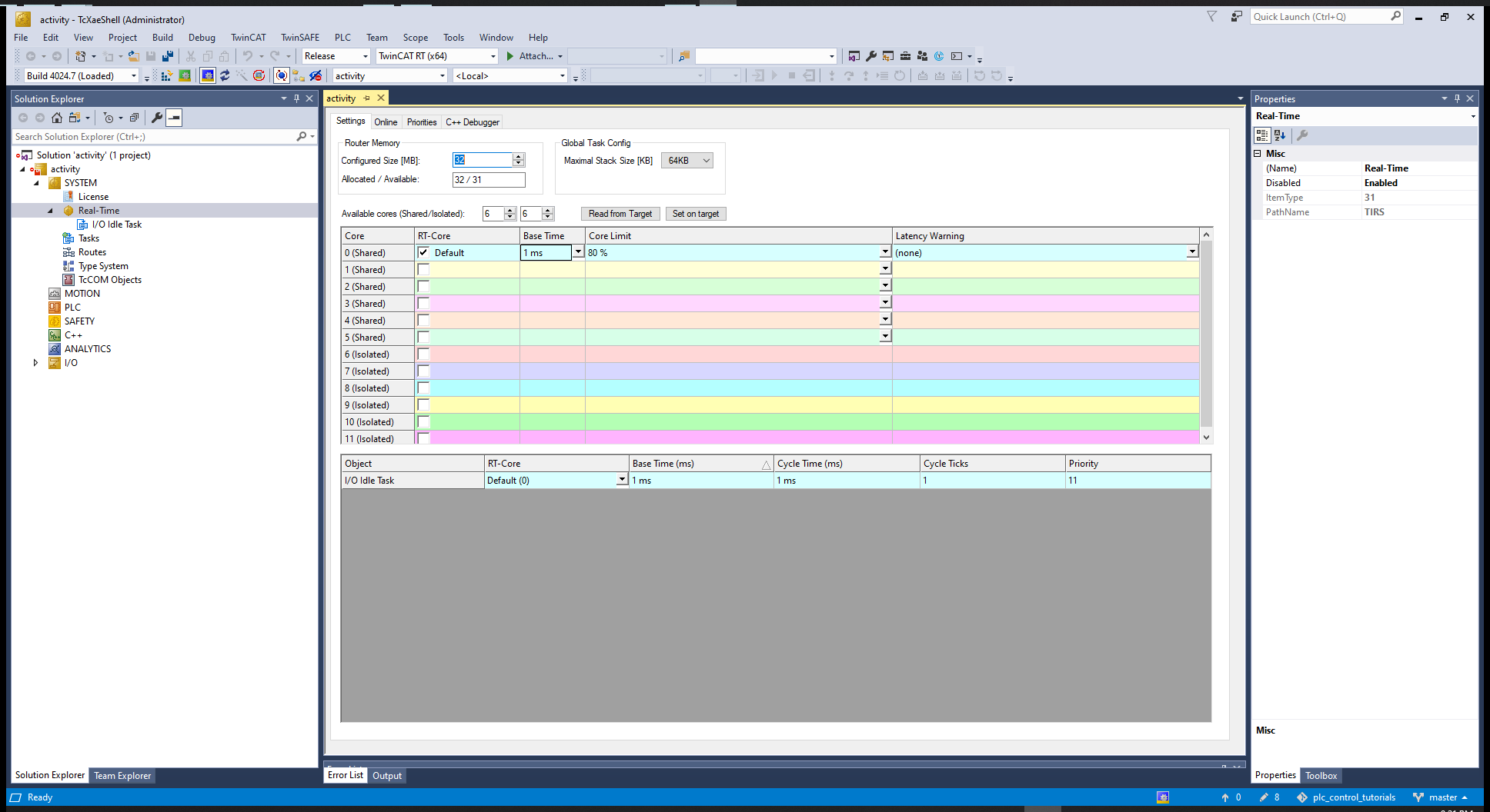
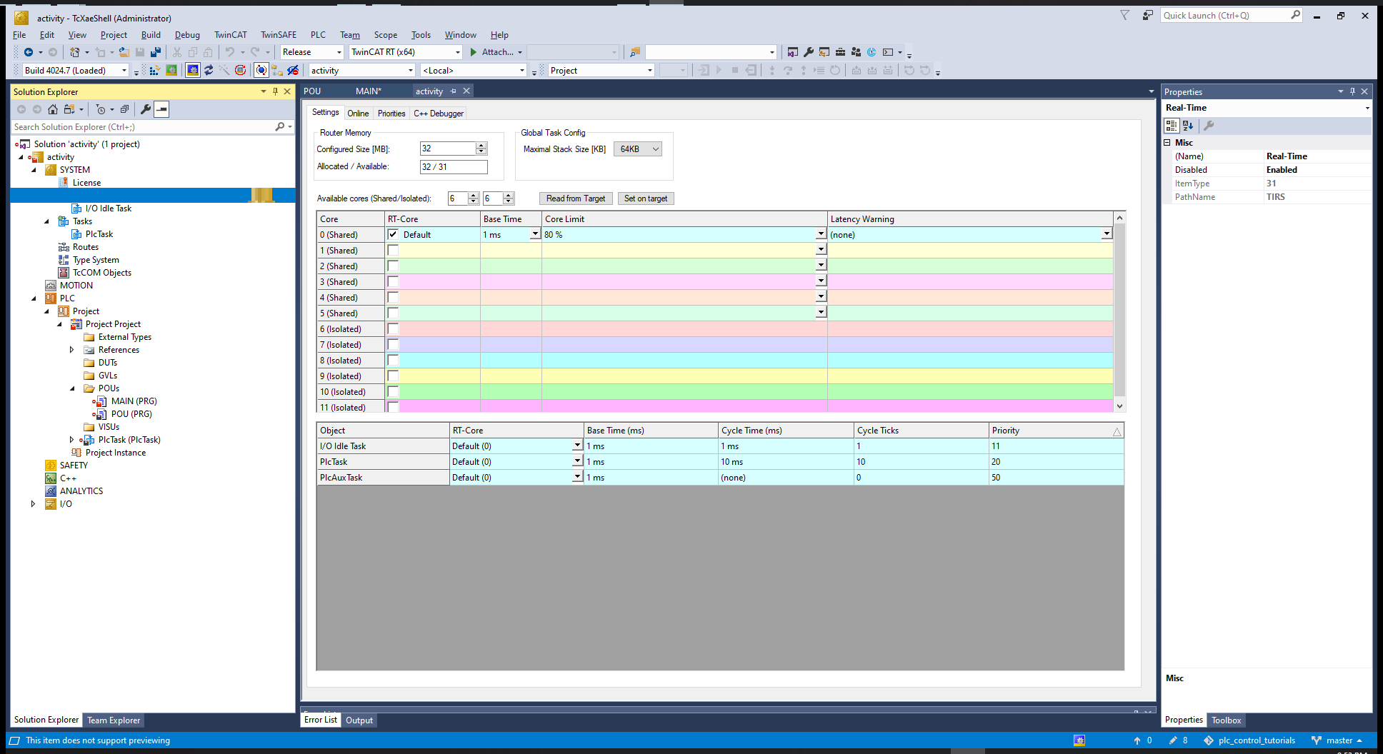
# Real-Time - CPU cores
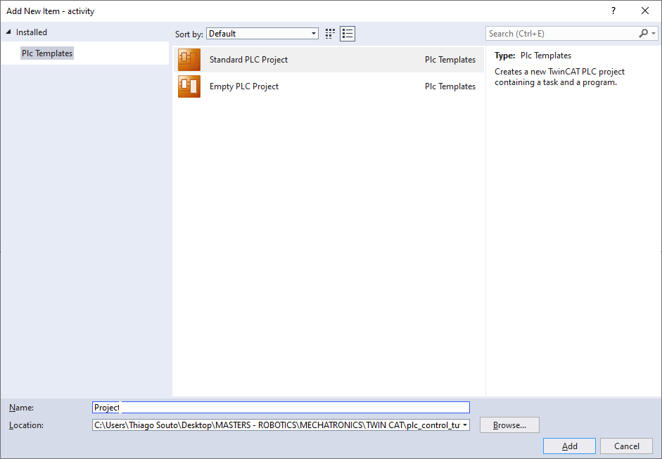
# PLC
# Creating PLC new Item
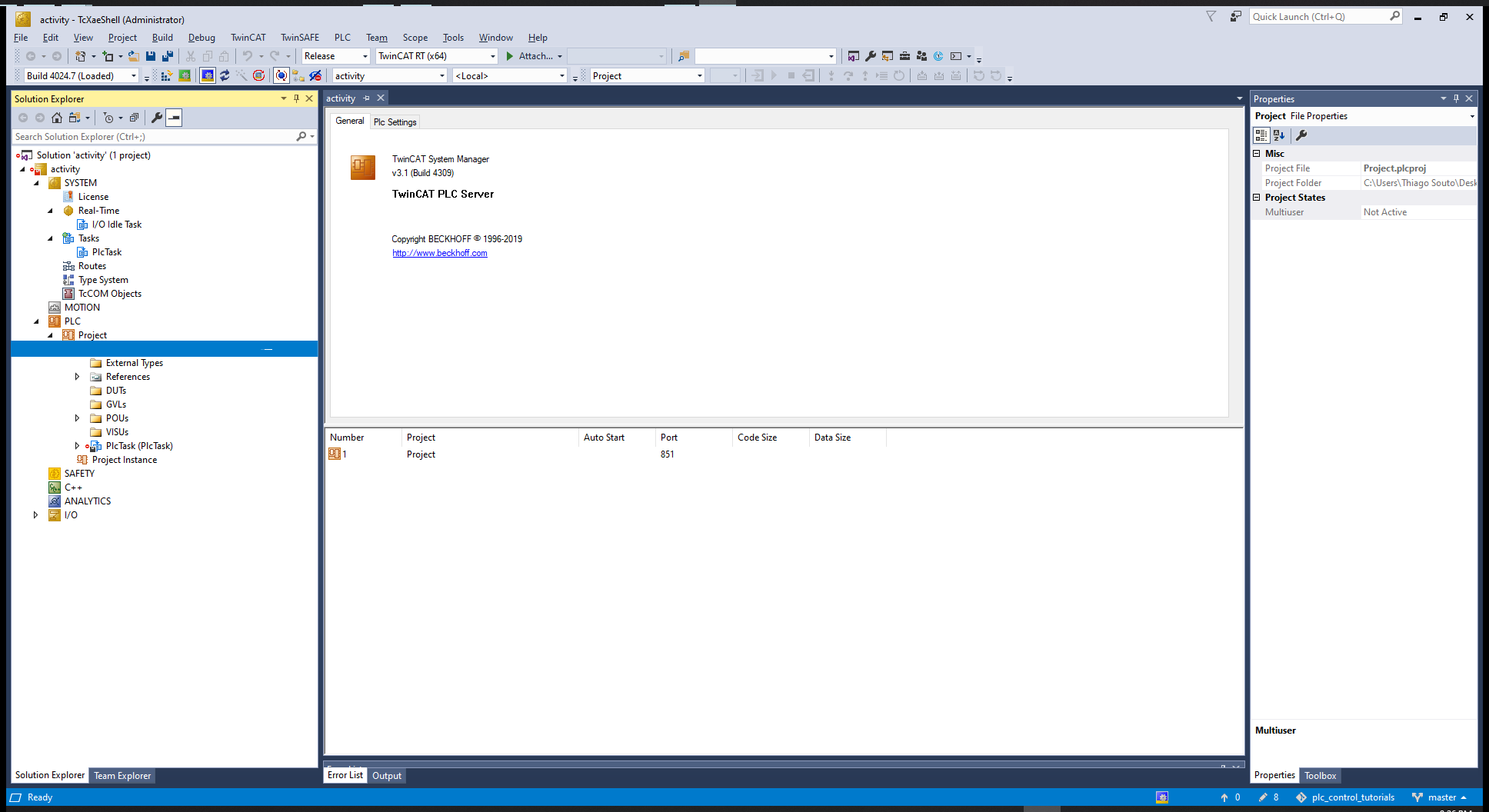
# Some definition inside the project:
| ID | Definition | Explanation |
|---|---|---|
| DUTs | User defined data types | Structures created |
| GVLs | Global Variables | Global variables like in C++, accessible to all files in the project |
| POUs | Program Organized Units | Where the MAIN program is located |
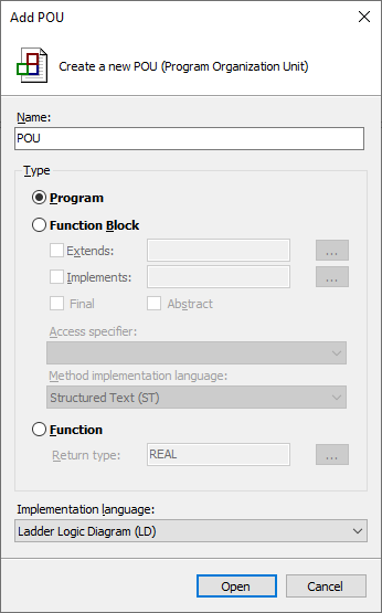
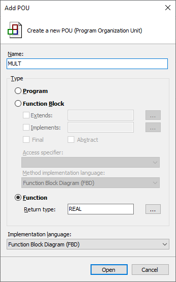
# New POU
We can choose between various languages:
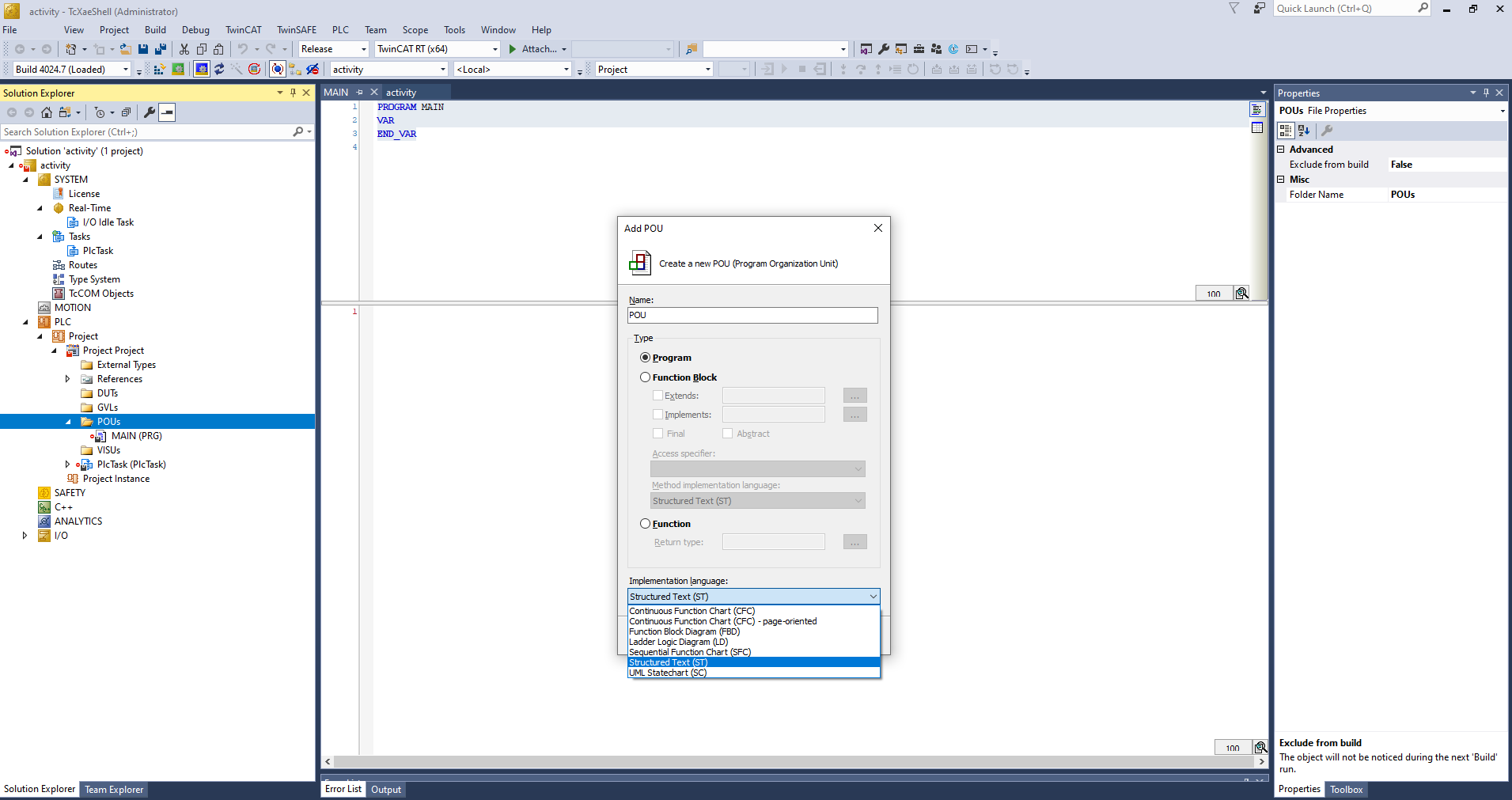
We now have to include in the MAIN program 'POU();' and this will run POU in the MAIN while loop as fast as the computer can based on the cicle time selected in the "Real-time", in this case 1ms.
MAIN:
PROGRAM MAIN
VAR
END_VAR
---------------------------
POU();
2
3
4
5
POU:
PROGRAM MAIN
VAR
END_VAR
---------------------------
2
3
4
5
6
# PlcTask
Looking at Cycle ticks we can see that the program will run once every 10 ms.
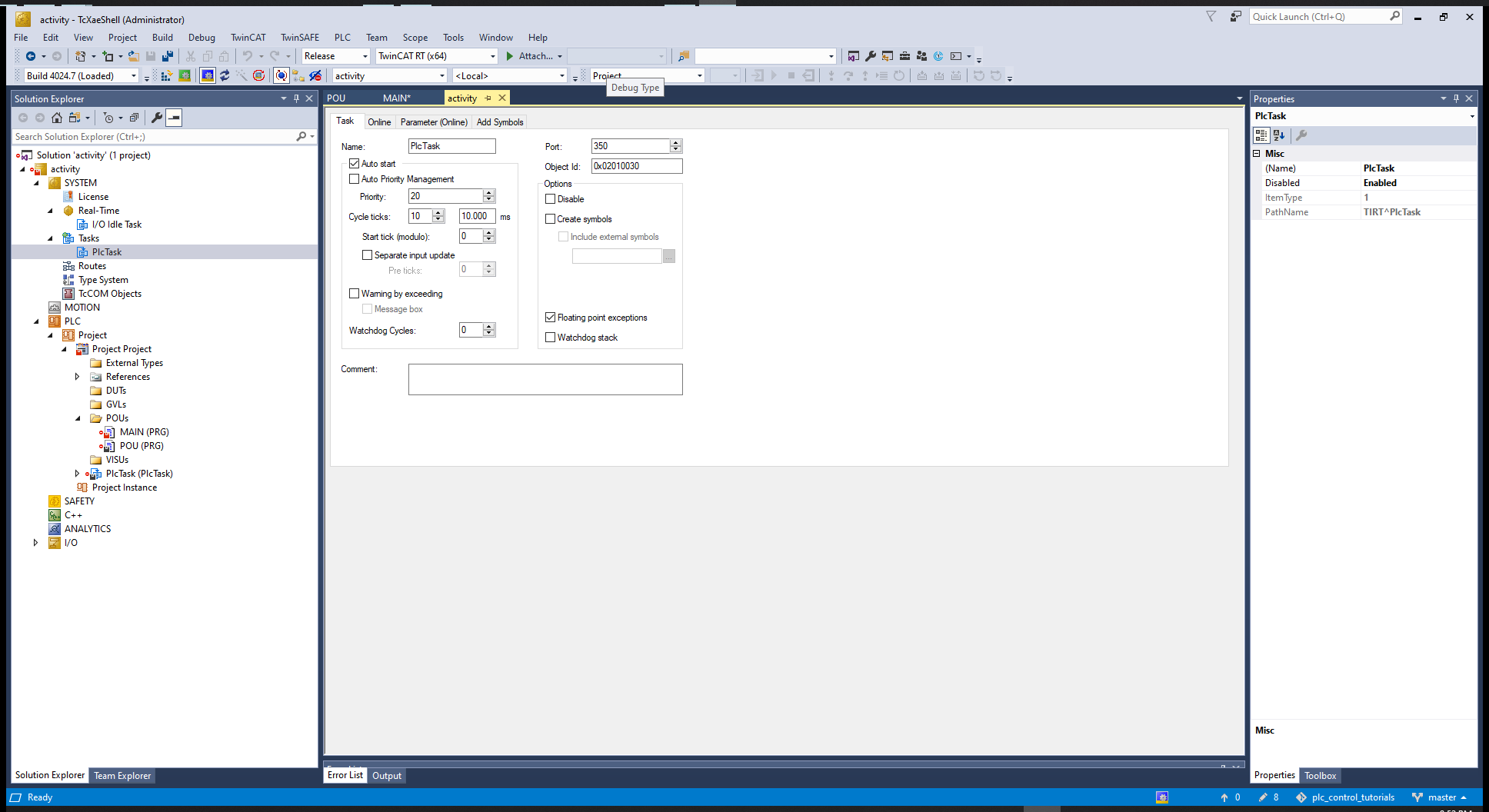
The Cycle ticks are based on the Base Time defined at the "Real-Time" window, in this case 1 ms
Looking back at the Cycle ticks we can sse that it's going to wake up every 10 Base times and 10*1ms = 10ms.
# Connecting the computer to a hardware
PLCs have inputs and Outputs, so we can define variables in the program as inputs, and we can map those inputs with the hardware pins. In order to describe an input we have to describe a variable name.
Variable 'A' which is an input variable '%I*' of the type Boolean.
PROGRAM POU
VAR
	A AT %I* : BOOL;
	B AT %I* : BOOL;
	A AT %Q* : BOOL := TRUE;

END_VAR
2
3
4
5
6
7
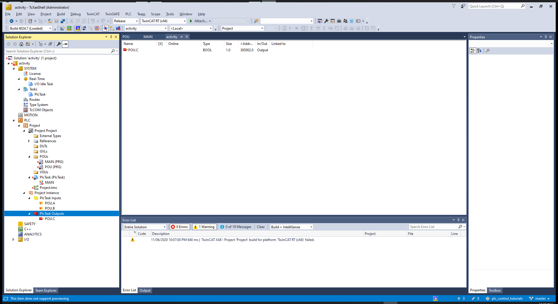
After building and run we can see the inputs and outputs:
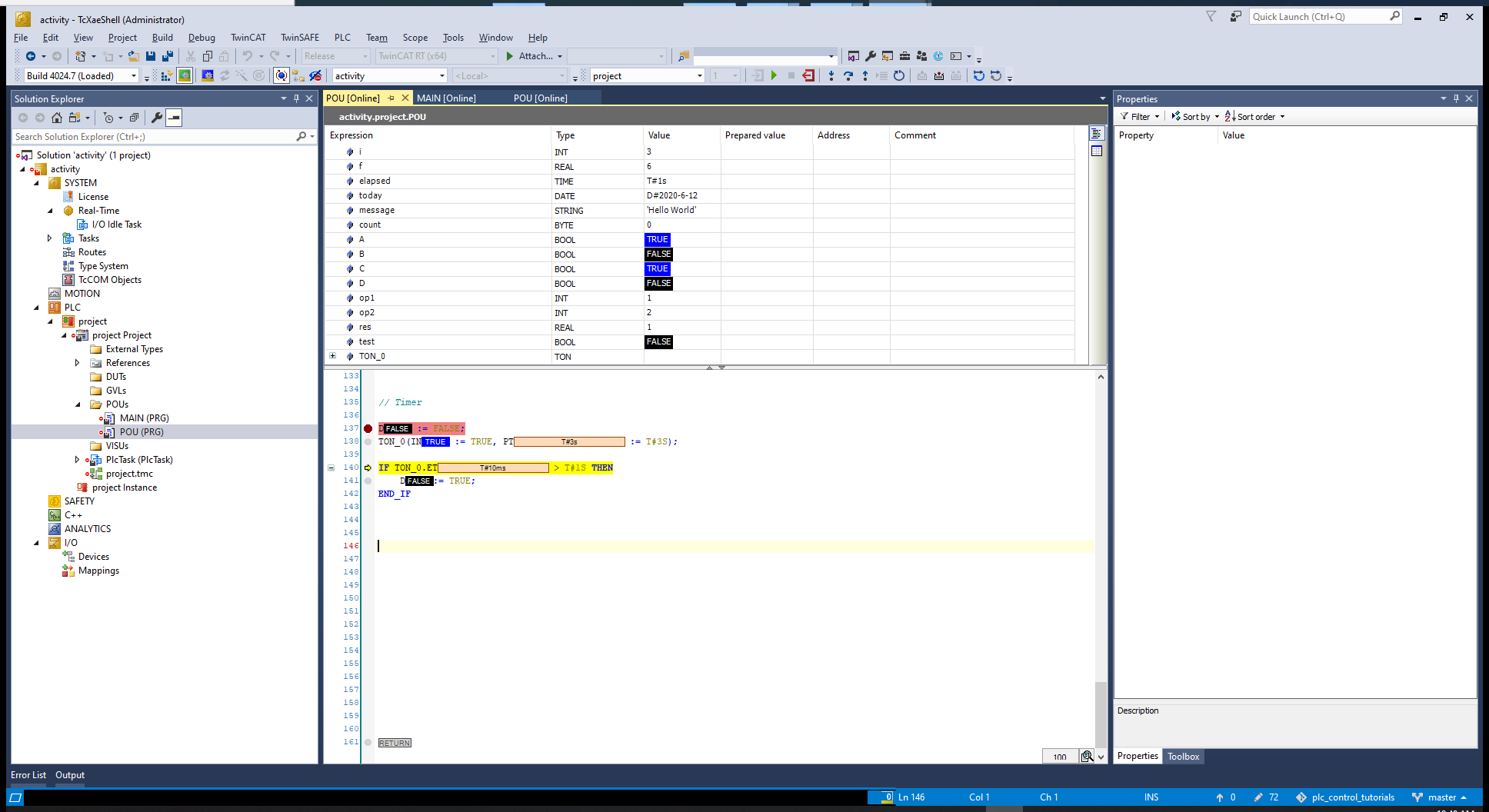
# First Program
PROGRAM POU
VAR

	i : INT := 0;
	f : REAL := 0.0;
	elapsed : TIME := TIME#0M0S0MS;
	today : DATE := DATE#2020-06-12;
	message : STRING := '';
	count : BYTE := 0;

	A : BOOL := FALSE;
	B : BOOL := FALSE;
	C : BOOL := FALSE;
	D : BOOL := FALSE;

	op1 : INT := 1;
	op2 : INT := 2;
	res : REAL := 0.0;
	test : BOOL := FALSE;

	TON_0 : TON;

END_VAR
---------------------------

// Single line comment

(*
	Multiple line comment
*)

i := 0;
f := 0.0;
elapsed := T#1S;
today := D#2020-06-12;
message := 'Hello World';

// Operators

test := A AND ( A AND B );

res := MAX(op1, op2);

res := EXPT(op1, op2);

res := -op1;
B := NOT A;

res := op1 * op2;
res := op1 / op2;
res := op1 MOD op2;

test := op1 < op2;
test := op1 > op2;
test := op1 <= op2;
test := op1 >= op2;

C := A AND B;

C := A XOR B;

C := A OR B;

// IF statements

IF A = B THEN
	D := TRUE;
END_IF


IF A = B THEN
	D := TRUE;
ELSE
	D := FALSE;
END_IF


IF A = B THEN
	D := TRUE;
ELSIF A = C THEN
	D := FALSE;
END_IF


// CASE

i := 0;

CASE i OF
	0 : A:= TRUE;
	1 : B:= TRUE;
	2 : C:= TRUE;
ELSE
	D := TRUE;
END_CASE


// FOR loops

f := 0.0;

FOR i := 0 TO 5 BY 1 DO
	f := f + 1.0;
END_FOR


f:= 0.0;

FOR i := 0 TO 5 BY 1 DO
	f := f + 1.0;

	IF (f > 5) THEN
		EXIT;
	END_IF

END_FOR


// WHILE loops

i := 0;
F := 0.0;

WHILE f < 50 DO
	i := i +1;
	f := f + i;

	IF f > 5 THEN
		EXIT;
	END_IF

END_WHILE


// REPEAT loop

i := 0;
f := 0.0;

REPEAT
	i := i + 1;
	f := f + i;
UNTIL f >= 5
END_REPEAT

i := 0;
f := 0.0;

REPEAT
	i := i + 1;
	f := f + i;

	IF f > 5 THEN
		EXIT;
	END_IF
UNTIL f > 50
END_REPEAT


// Timer

D := FALSE;
TON_0(IN := TRUE, PT := T#3S);

IF TON_0.ET > T#1S THEN
	D:= TRUE;
END_IF
2
3
4
5
6
7
8
9
10
11
12
13
14
15
16
17
18
19
20
21
22
23
24
25
26
27
28
29
30
31
32
33
34
35
36
37
38
39
40
41
42
43
44
45
46
47
48
49
50
51
52
53
54
55
56
57
58
59
60
61
62
63
64
65
66
67
68
69
70
71
72
73
74
75
76
77
78
79
80
81
82
83
84
85
86
87
88
89
90
91
92
93
94
95
96
97
98
99
100
101
102
103
104
105
106
107
108
109
110
111
112
113
114
115
116
117
118
119
120
121
122
123
124
125
126
127
128
129
130
131
132
133
134
135
136
137
138
139
140
141
142
143
144
145
146
147
148
149
150
151
152
153
154
155
156
157
158
159
160
161
162
163
164
165
166
167
After building the solution go to Activate Configuration, to configure the hardware:

Then login to the PLC
and run:
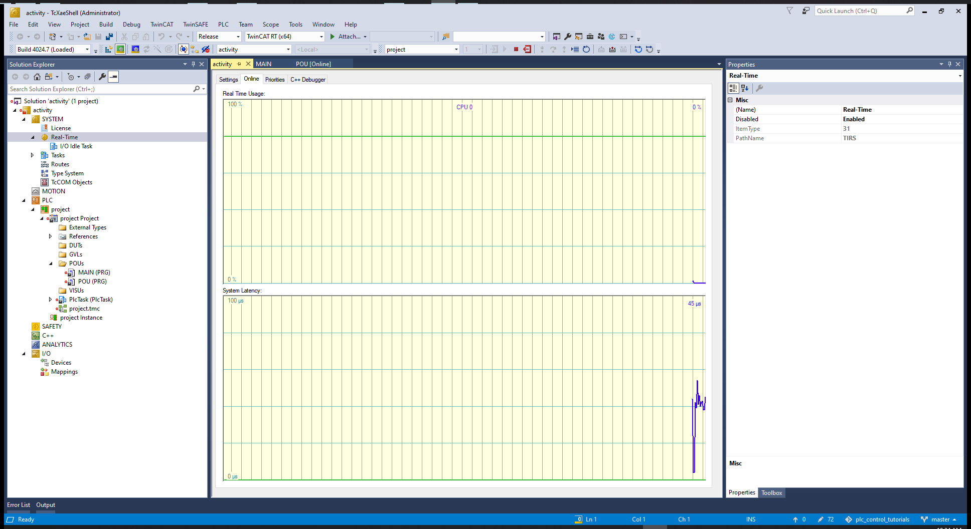
At "Real-Time", Online we can check the CPU usage:
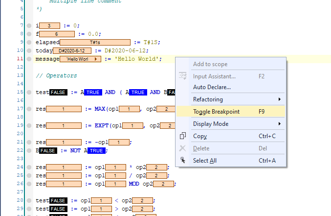
We can toggle break points to debug
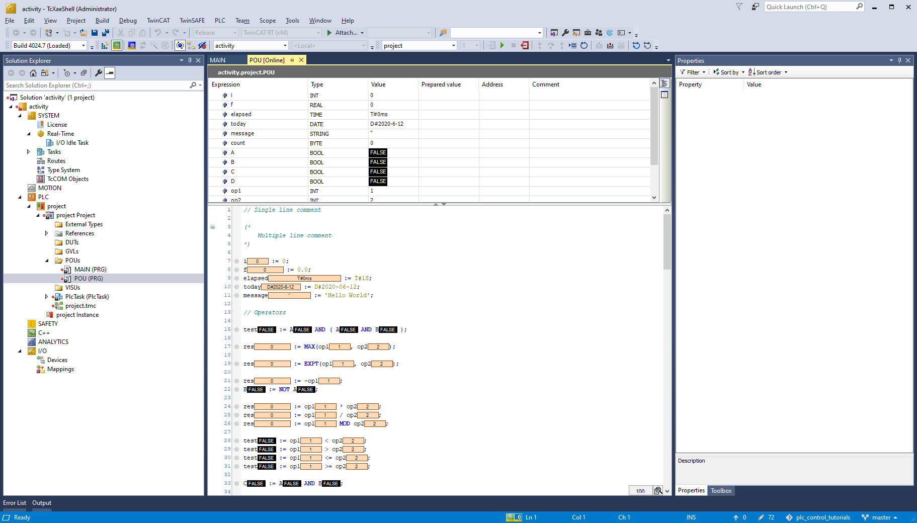
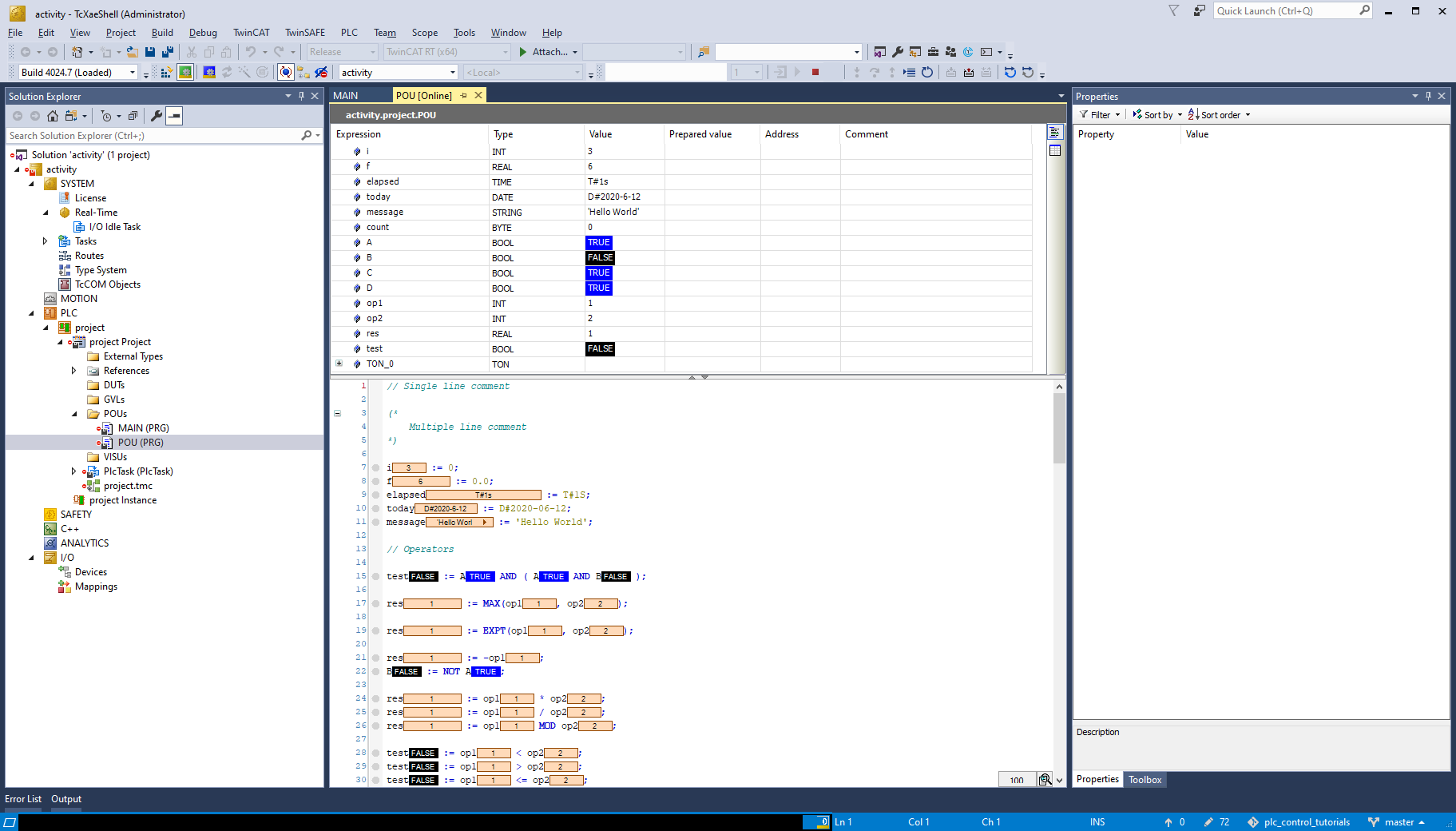
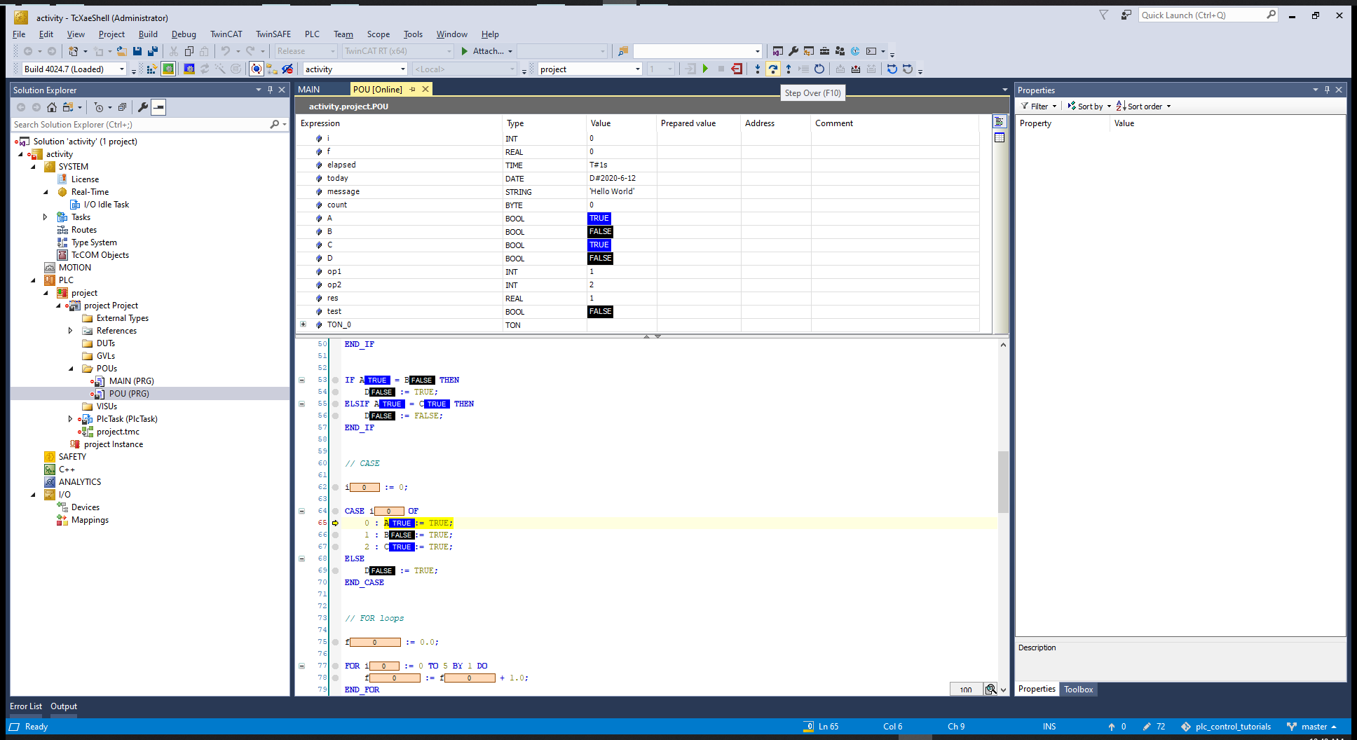
Run Through the program and check the values
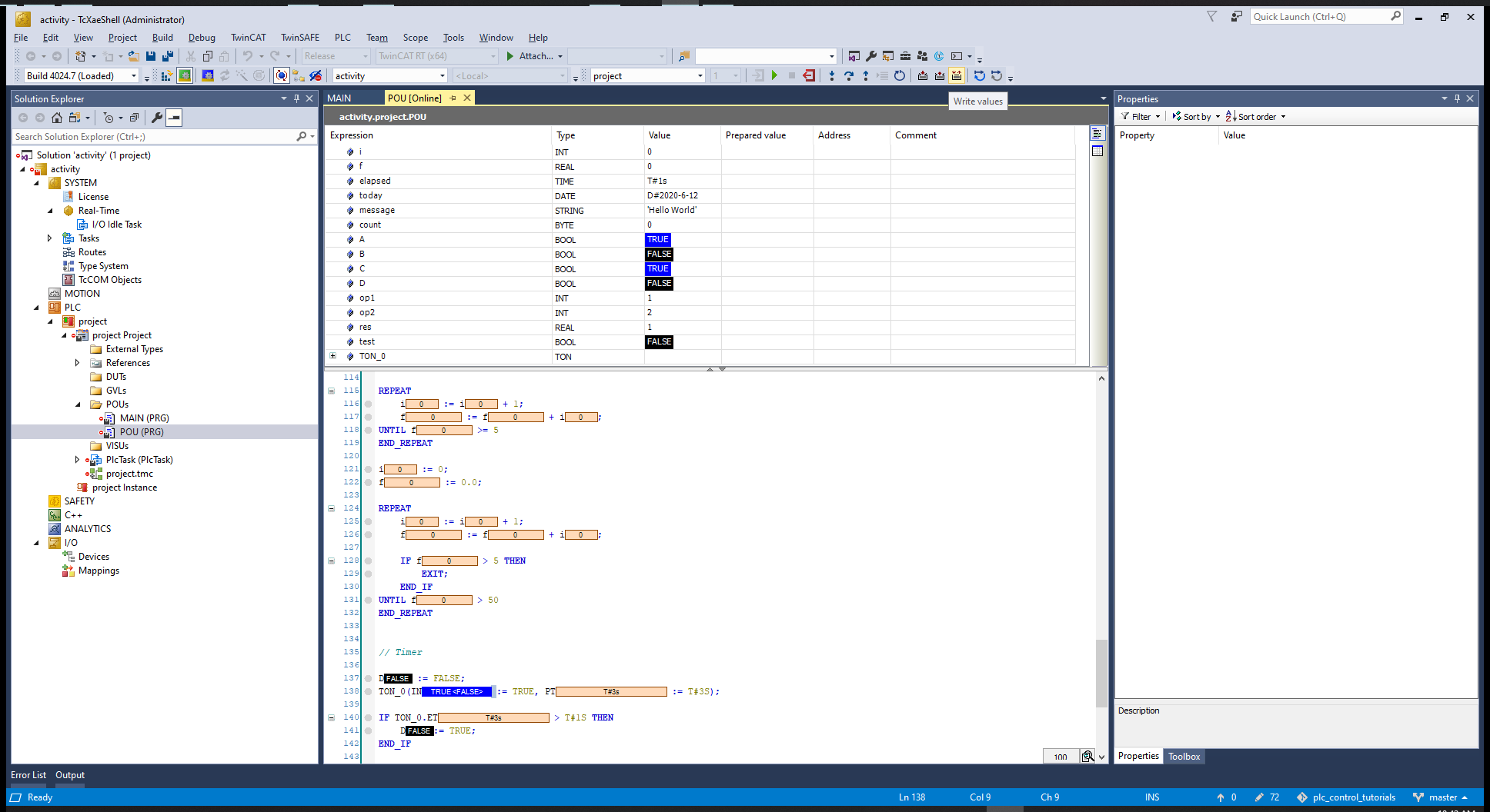
We can go to a value and right values and use the button Write values
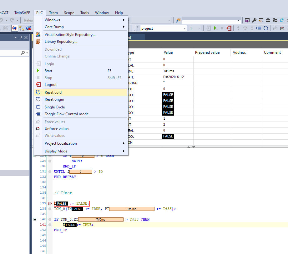
To reset the values we can logout then login and do a reset cold
We can notice that the timer has elapsed 10ms as set on the "Real-Time"
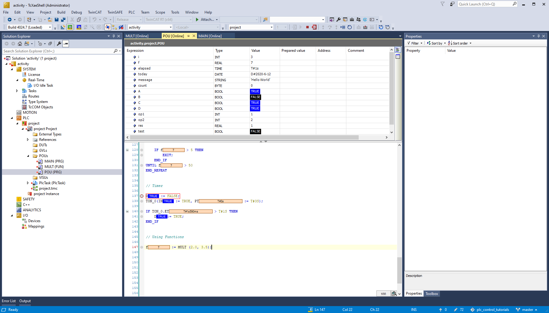
# Functions
Go to POU and add an item
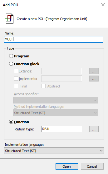
Write the function;
Add to POU and check the results:
# Sample Problem
- A conveyor and a mechanism are used to sort red and black objects into their corresponding bins. The conveyor has a sensor at its beginning that is used to detect an object's color. When an object is detected, the conveyor's motor turns on. When an object is detected, an actuator may move its attached linkage to sort the object into its proper bin. Objects take at least 1 second to be sorted after being detected. After an object has been sorted, the conveyor's motor turns off. After an object has been sorted, if the actuator moved its attached linkage, it moves back to its default location.
In Structure Text (ST), write a program that implements the described system's steps.
Check your solutions against those in solution's POU_1 program.
MAIN:
PROGRAM MAIN
VAR
END_VAR
---------------------------
POU_1();
2
3
4
5
POU_1:
PROGRAM POU_1
VAR

	objectDetected : BOOL := FALSE;

	blackObject : BOOL := FALSE;
	redObject : BOOL := FALSE;

	motorOn : BOOL := FALSE;
	actuatorMove : BOOL := FALSE;

	objectSorted : BOOL := FALSE;

	startTimer : BOOL := FALSE;
	TON_0 : TON;

END_VAR
---------------------------
TON_0(IN := startTimer, PT := T#5S);

IF objectDetected = TRUE THEN

	objectSorted := FALSE;

	IF redObject = TRUE THEN
		actuatorMove := TRUE;
	END_IF

	startTimer := TRUE;
	motorOn := TRUE;

END_IF

IF TON_0.ET > T#1S THEN

	motorOn := FALSE;
	startTimer := FALSE;
	actuatorMove := FALSE;

	objectSorted := TRUE;

END_IF
2
3
4
5
6
7
8
9
10
11
12
13
14
15
16
17
18
19
20
21
22
23
24
25
26
27
28
29
30
31
32
33
34
35
36
37
38
39
40
41
42
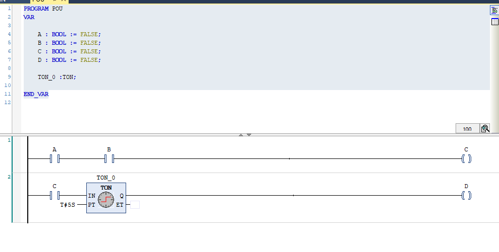
# Ladder
Create a new project, and add a PLC and create a POU:
Declaring the input and output variables
PROGRAM POU
VAR
	A AT %I* : BOOL := FALSE;
	B AT %I* : BOOL := FALSE;
	C AT %I* : BOOL := FALSE;
	D AT %Q* : BOOL := FALSE;
END_VAR
2
3
4
5
6
7
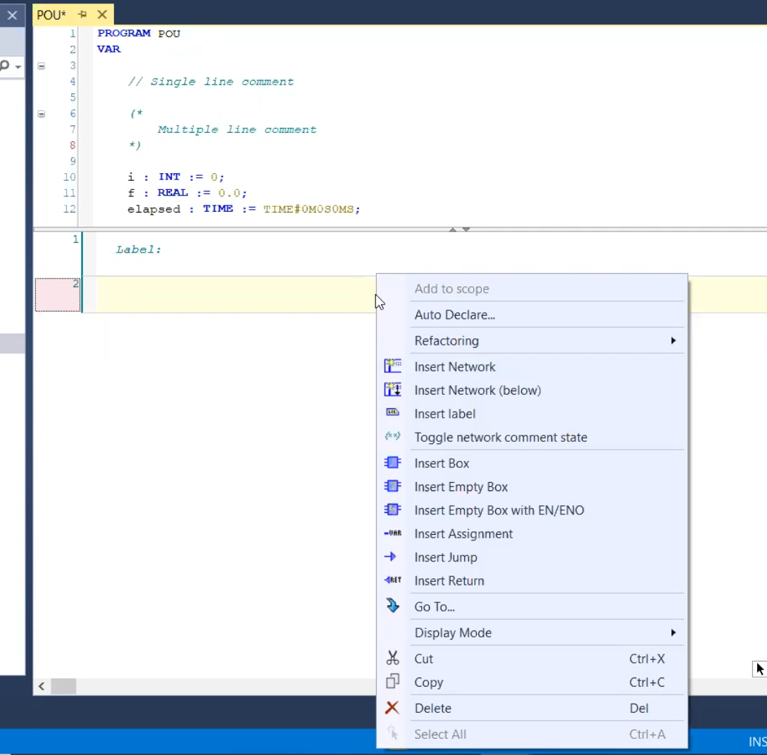
We can add labels and then toggle the state to a comment:
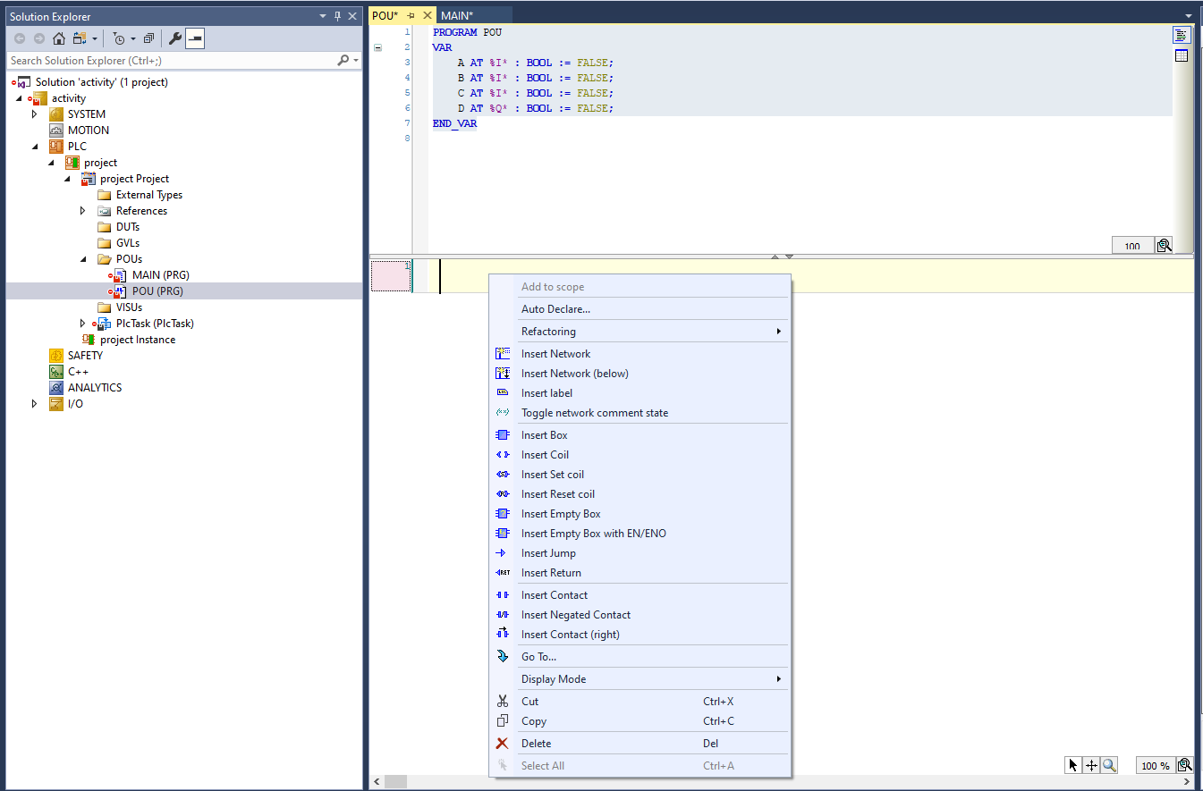
We can insert contacts, labels, coils...
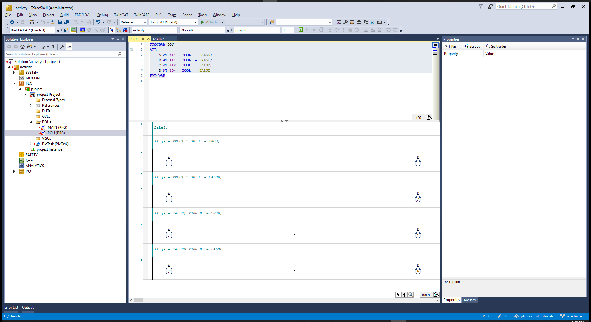
We can also negate an object or choose to set like the 3rd coil, when in set mode it will stay on after the contact is released, OR RESET.
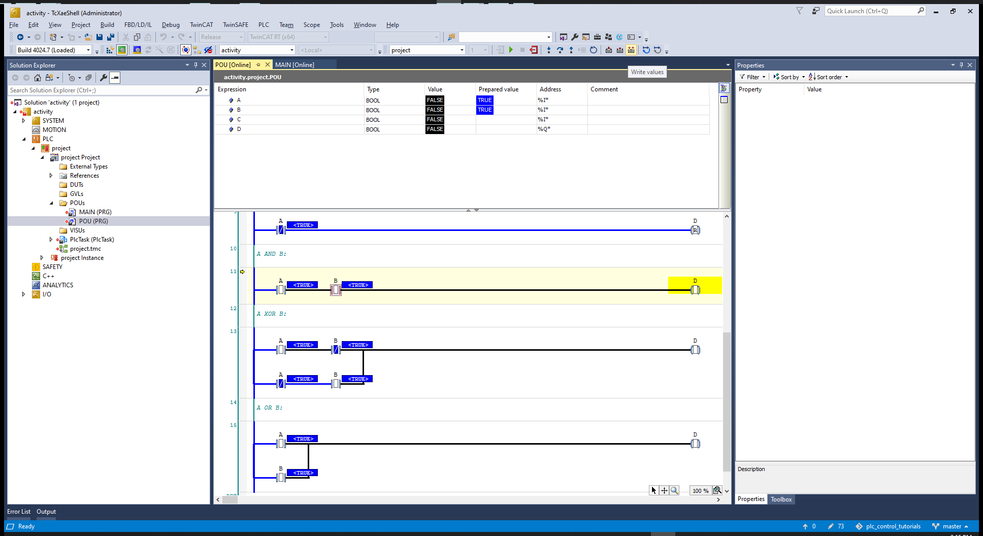
# Implementing boolean logic

Save it, activate, run mode, login to the PLC, create the port
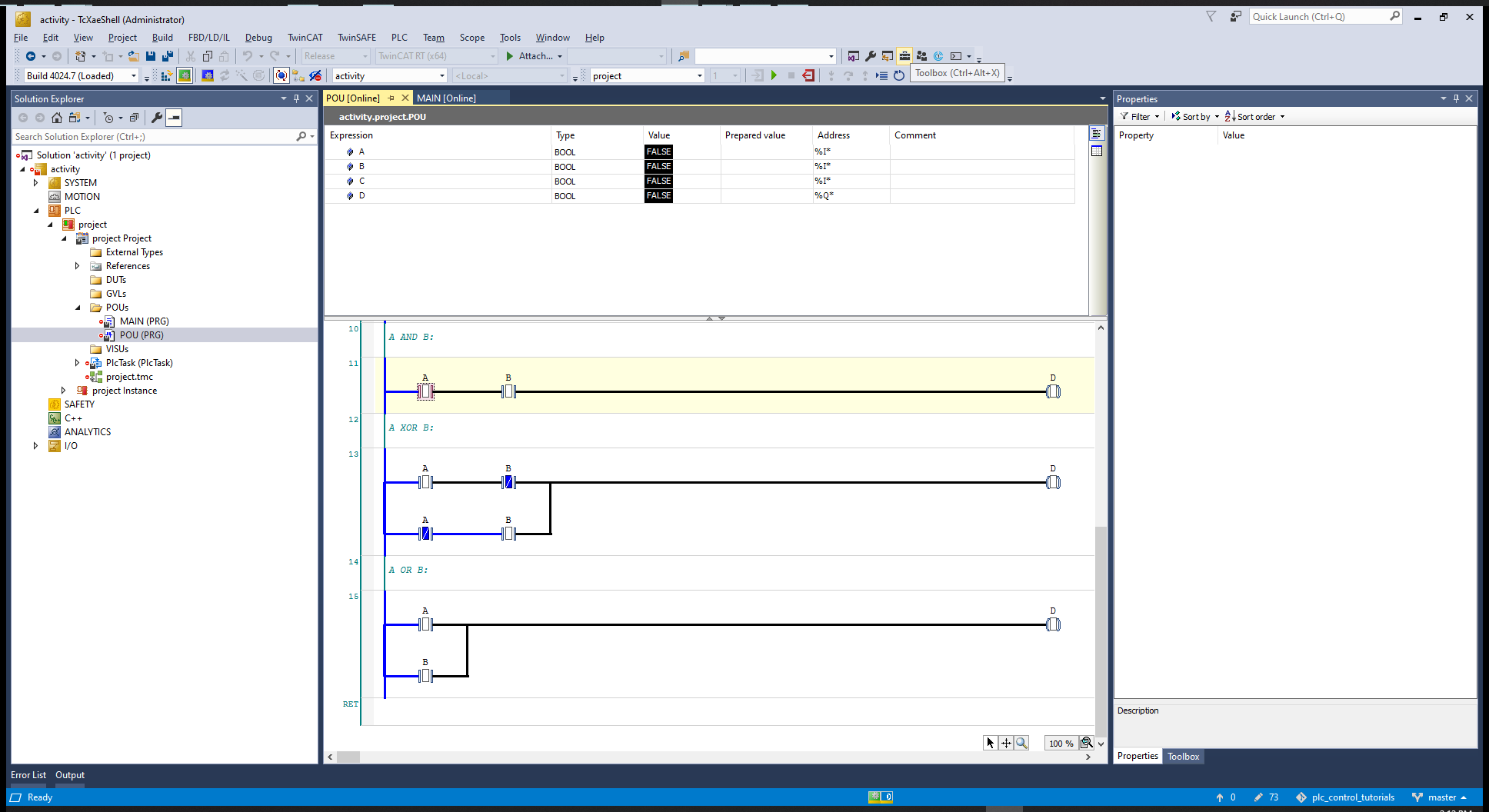
We can prepare and assign values by clicking on the contacts.
# FBD - Function Block Diagram
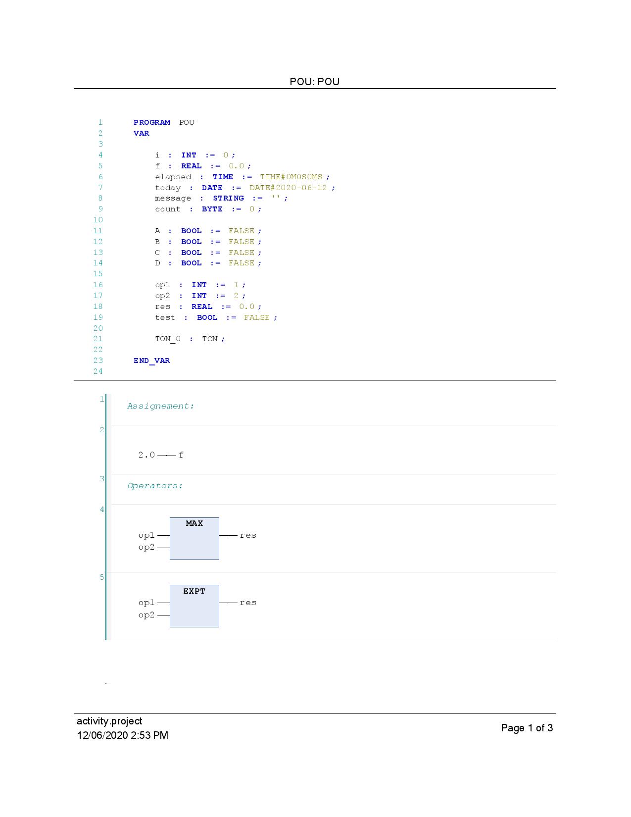
Create a new project, and add a PLC and create a POU, add the POU(); statement to the MAIN (PRG) and go to the POU to program it.
PROGRAM POU
VAR

	i : INT := 0;
	f : REAL := 0.0;
	elapsed : TIME := TIME#0M0S0MS;
	today : DATE := DATE#2020-06-12;
	message : STRING := '';
	count : BYTE := 0;

	A : BOOL := FALSE;
	B : BOOL := FALSE;
	C : BOOL := FALSE;
	D : BOOL := FALSE;

	op1 : INT := 1;
	op2 : INT := 2;
	res : REAL := 0.0;
	test : BOOL := FALSE;

	TON_0 : TON;

END_VAR
---------------------------
2
3
4
5
6
7
8
9
10
11
12
13
14
15
16
17
18
19
20
21
22
23
24
25
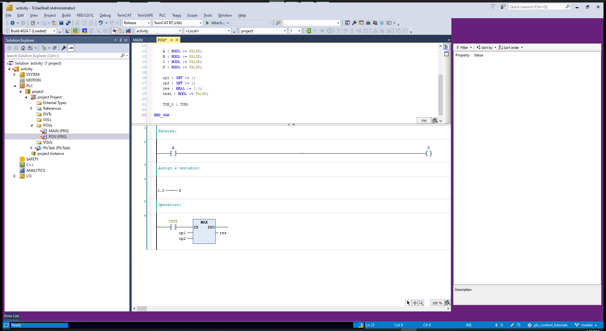
We can see that the options to include in the network are different from the Ladder program.
TIP
Use the arrow key to navigate through the network.
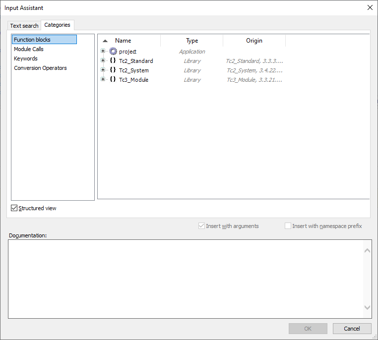
Insert a block and choose by navigating or by searching for the box name.
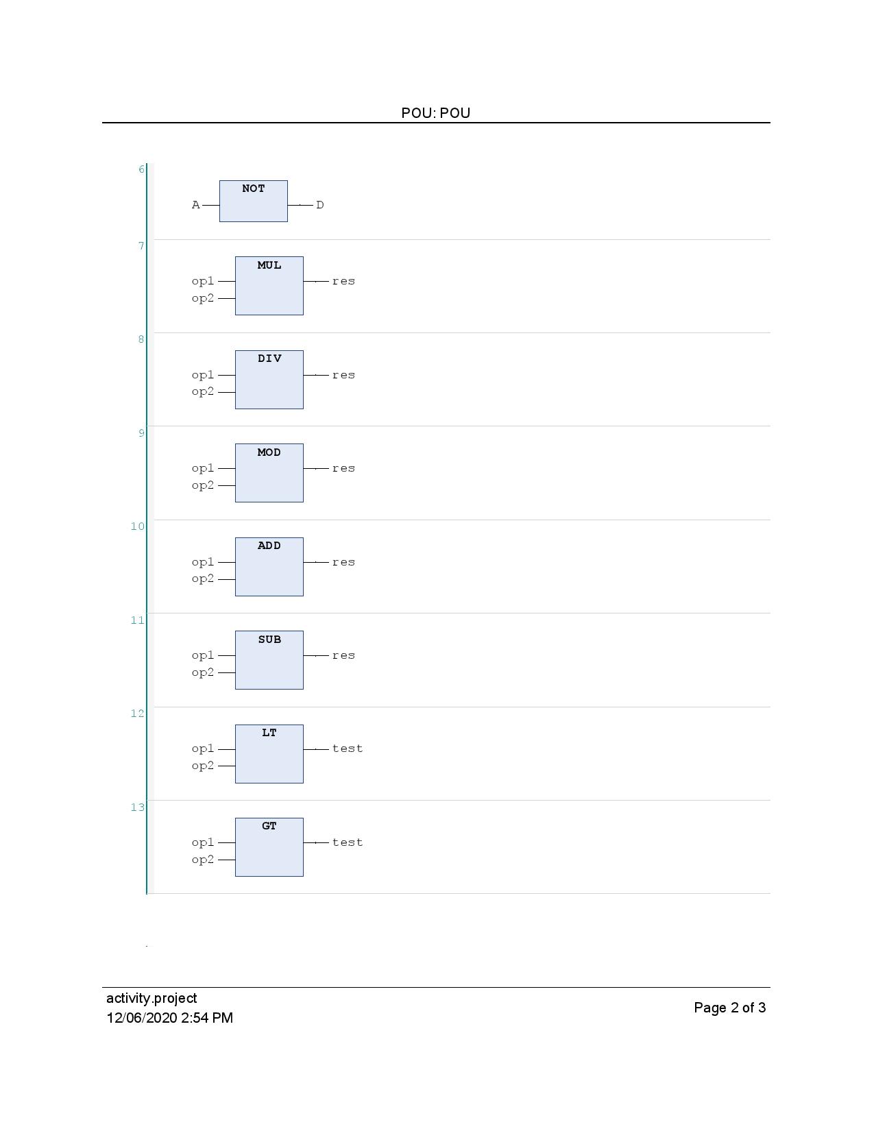
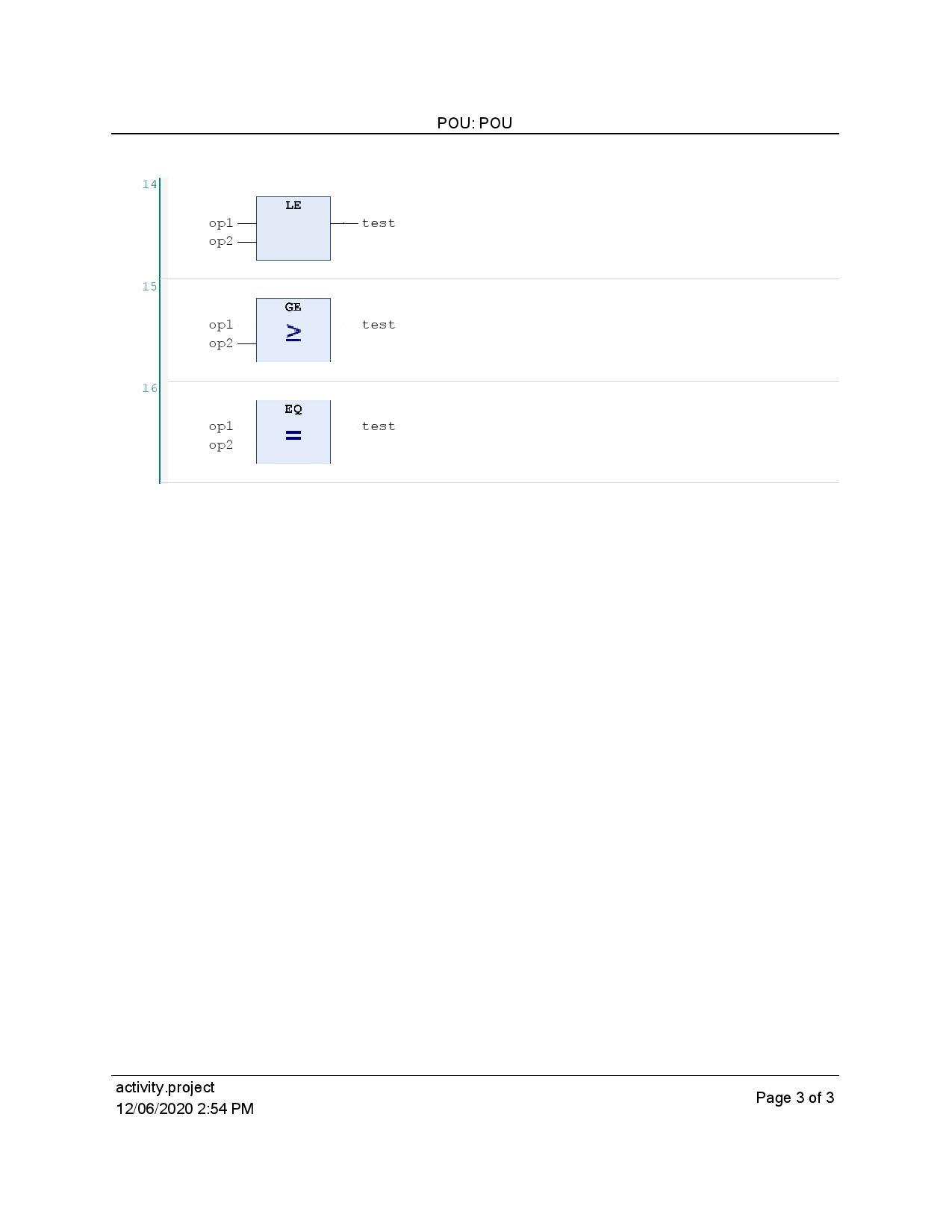
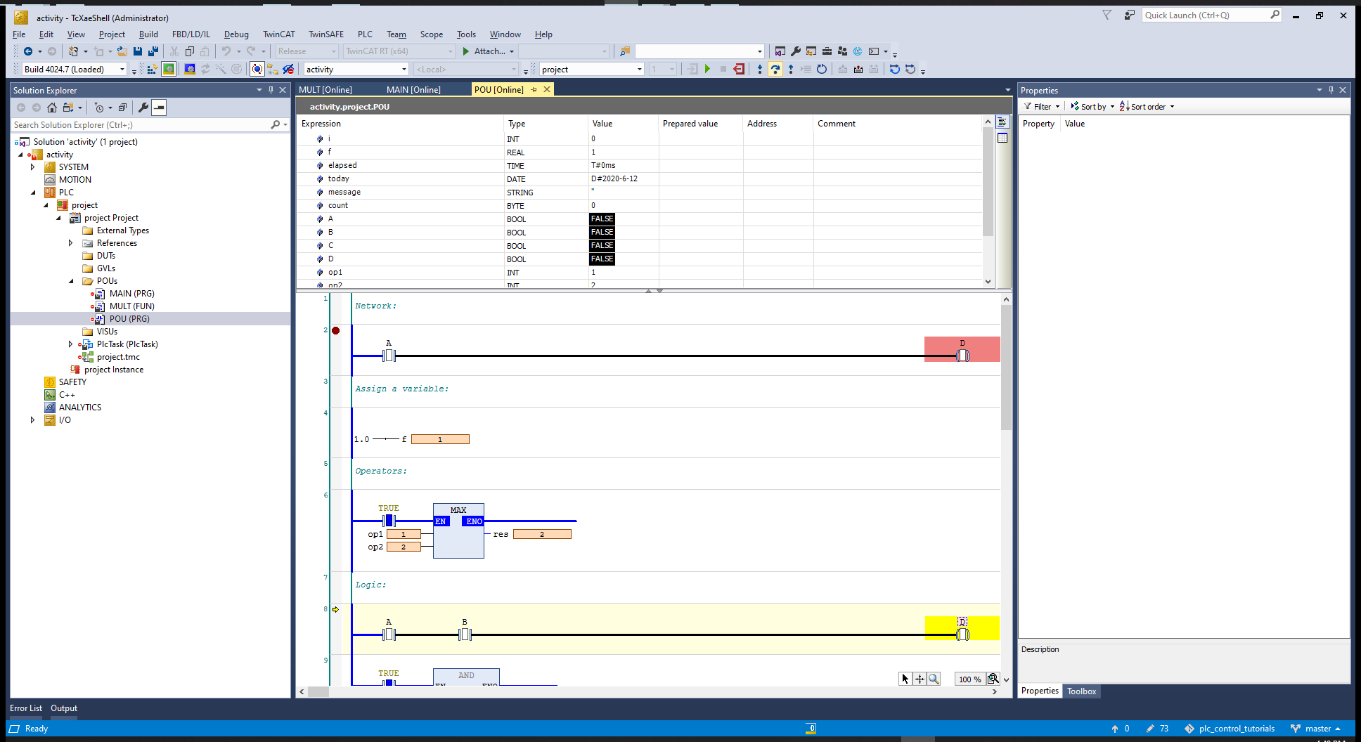
Insert the MAX block, then include the inputs op1 and op2 and assignment to the variable res.

Using all the logic blocks we have:
"Printed as PDF"
# Logic

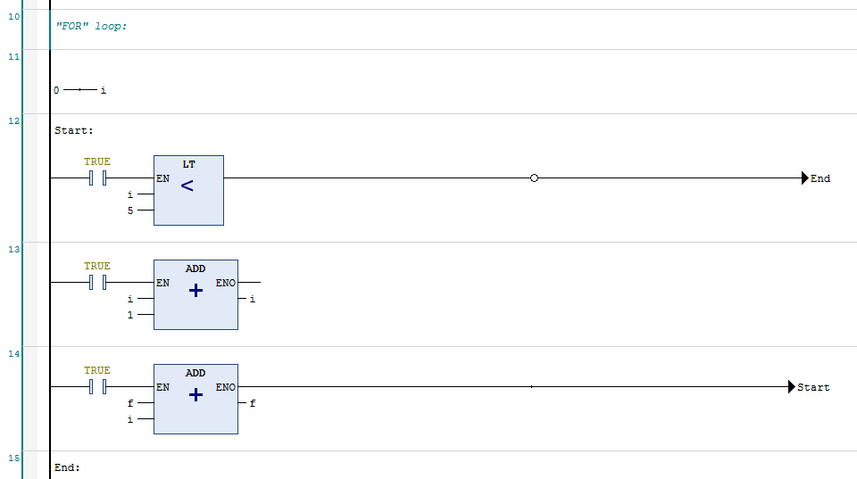
# For loop
For the FOR loop we can add a jump and negate the jump so if i is less than 5, then TRUE, then TRUE gets negated, and we don't jump.
Then we increment i with an ADD block in another network.
Then we execute what we want inside the for loop, in this case f.
Then we want to branch back to the start of our function, so we are going to jump to Start and set Start equal to TRUE.

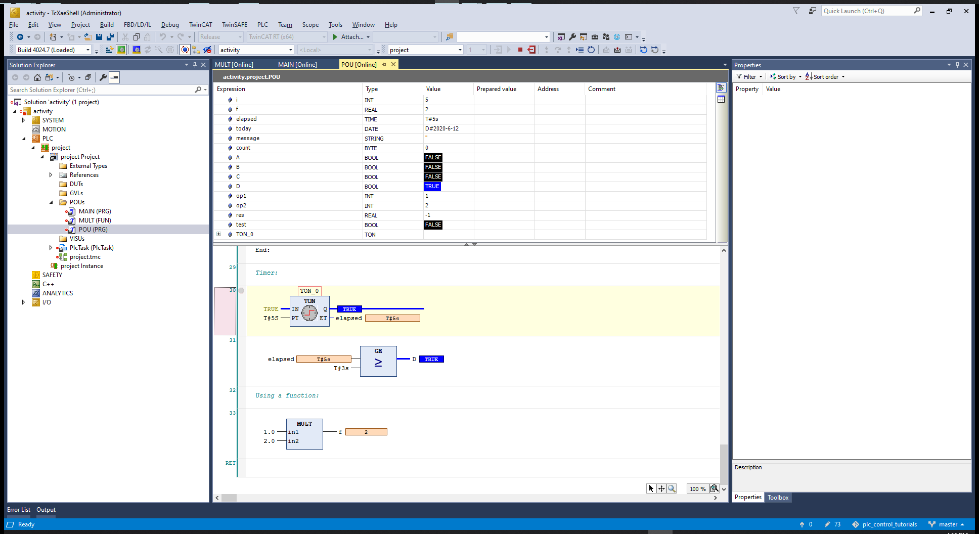
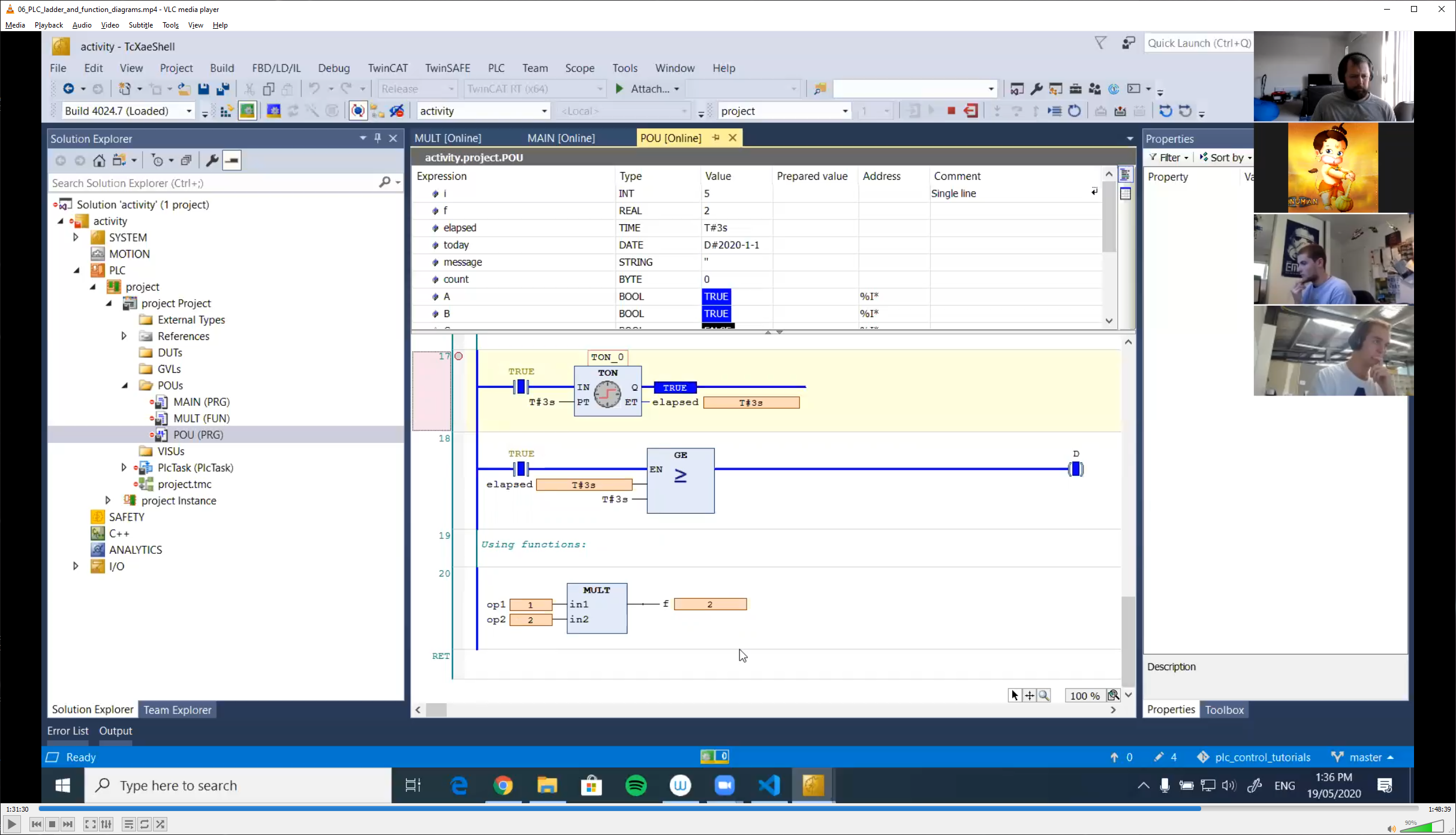
# Timers
We can insert a timer from the library
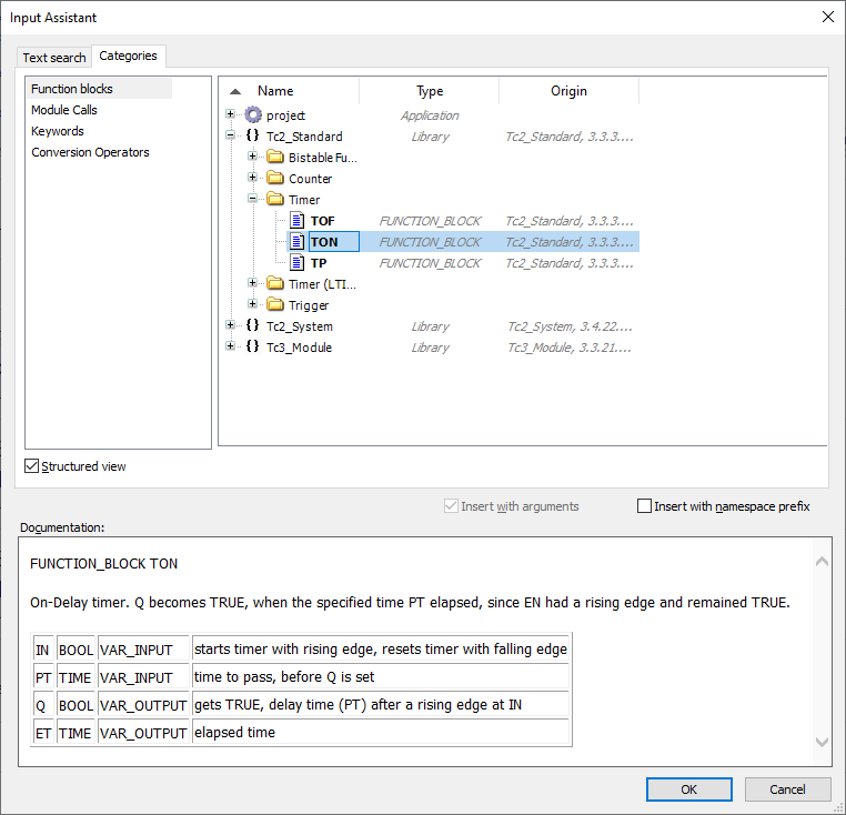
Now we are going to test if elapse is greater than 3 seconds and assign the output to D. We can use the values of Q and ET in other operators.

# Function
We have to add a new POU and to the POU we add a function that returns a REAL value.

Include a box and look for the function name.

Save all, build the project, Activate, Login to the PLC, create the port and run.
To debug go to the first executable line and add a break point.
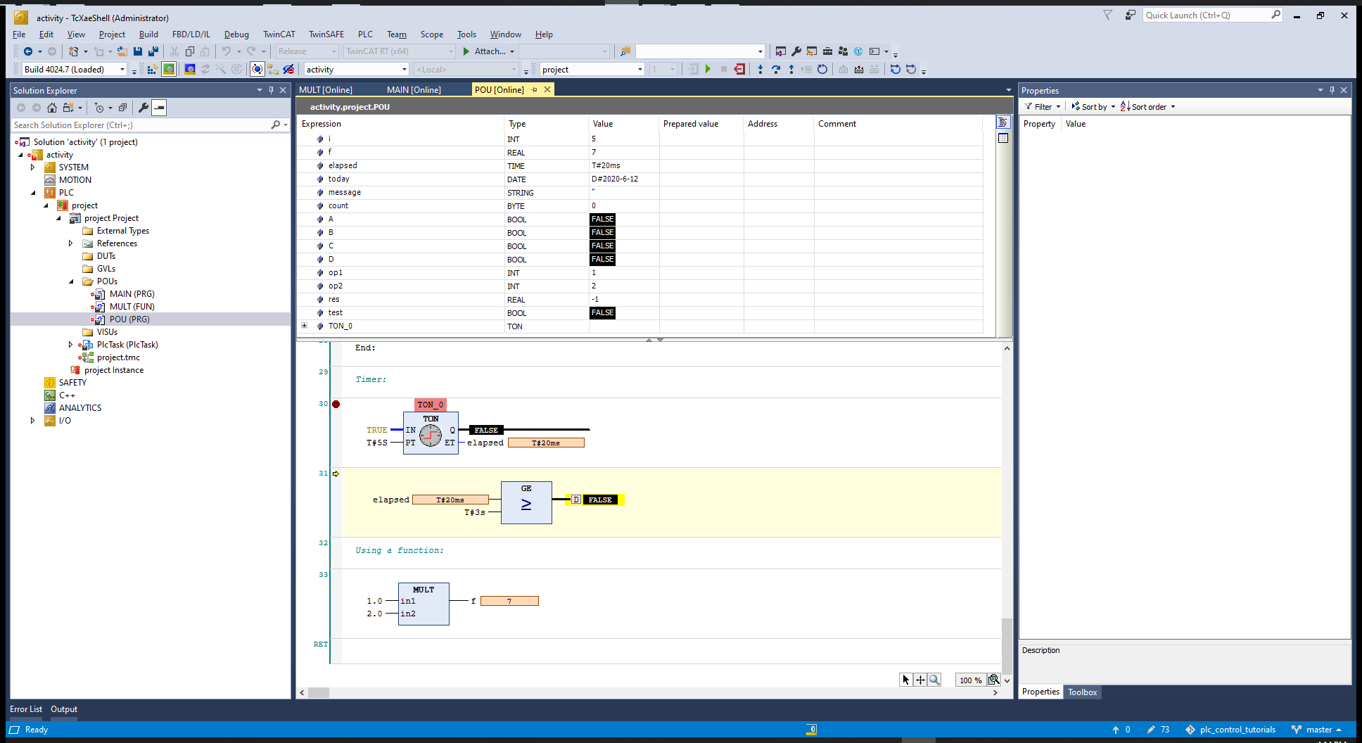
Every time the program runs the timer is incremented 10 ms. After 5s the timer sets the output to TRUE
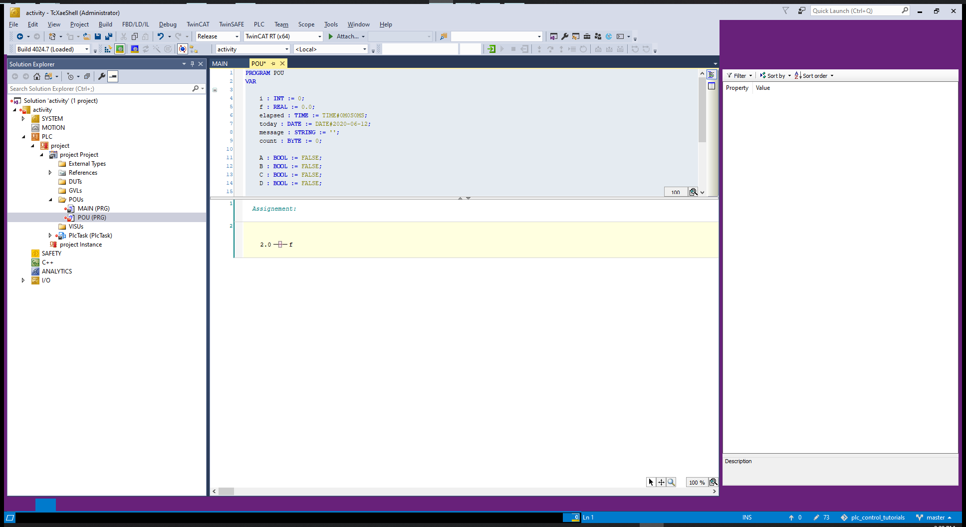
# Ladder + Function Block diagrams
Create a new project, and a PLC and create a POU, include the POU call at the main program.
to assign a value to a variable we create a contact and give the value, and then we creat a coil and give the variable name.


# Comparing the logic of Ladder and FBD

# For loop
# Timers

# Function
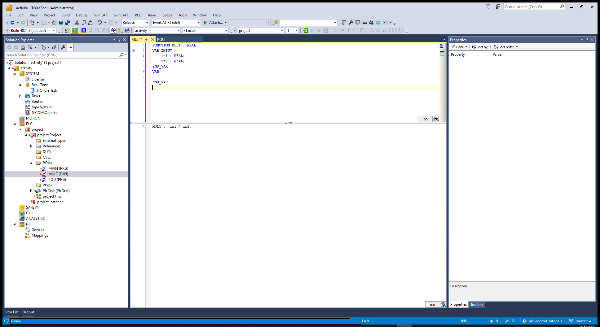
Create the function MULT with Structured text
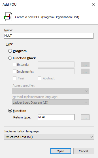
MULT:
FUNCTION MULT : REAL
VAR_INPUT
	in1 : REAL;
	in2 : REAL;
END_VAR
VAR
END_VAR
----------------------
MULT := in1 * in2;
2
3
4
5
6
7
8
9

Now activate configuration, this will put it on run mode, then login into the PLC, go to the top of the program and right click on the first run and toggle a breakpoint, then start the program and step through.
Or you can just run without breakpoints to execute the program.
As before, the timer is being incremented by 10 ms
And if we disable the brakpoint and run the program, at the end we can see that the variable turns TRUE.
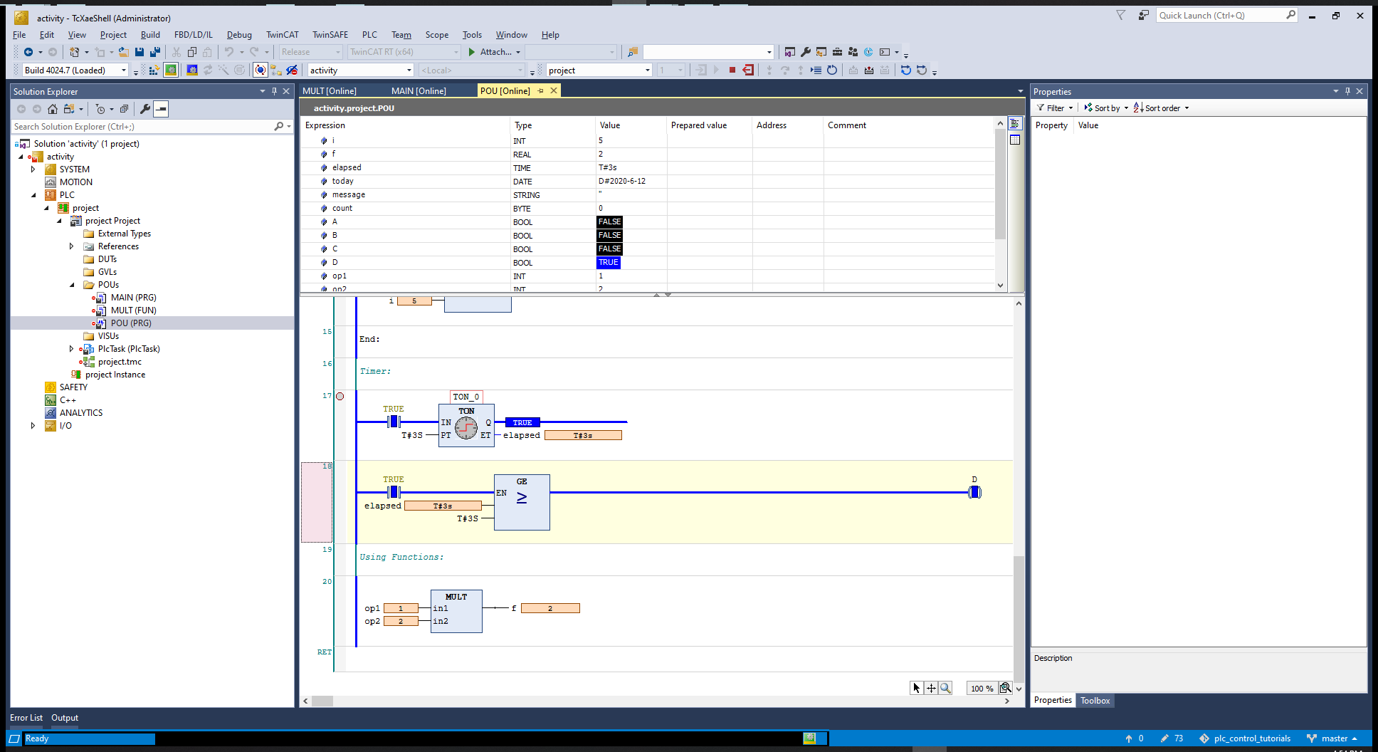
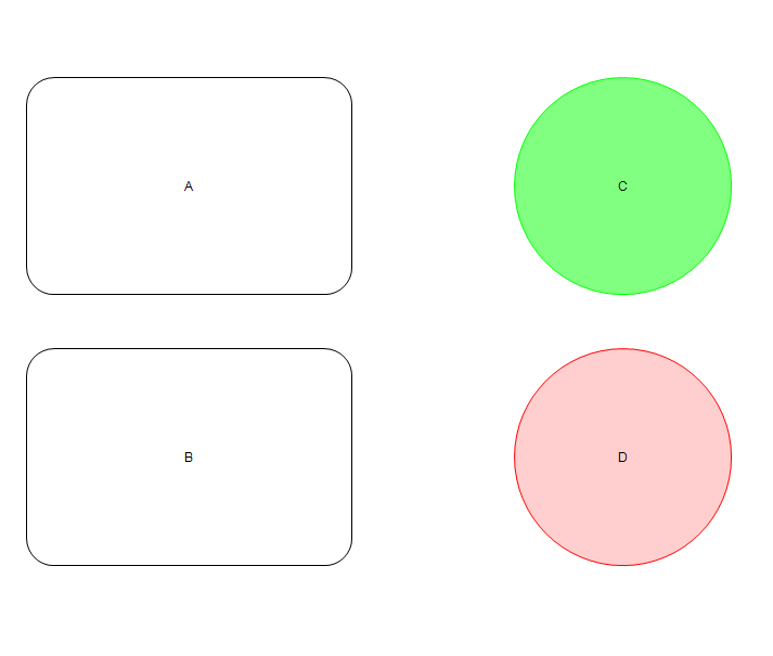
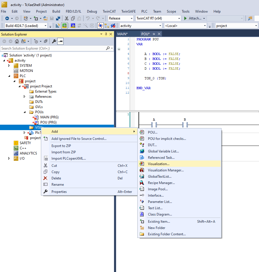
# Visualization
As before, create a new project, and add a PLC and create a POU, add the POU(); statement to the MAIN (PRG) and go to the POU to program it.
If (A and B) are TRUE, then enable C (C becomes TRUE), if C is TRUE start the timer, if the timer has elapsed enable D.
PROGRAM POU
VAR

	A : BOOL := FALSE;
	B : BOOL := FALSE;
	C : BOOL := FALSE;
	D : BOOL := FALSE;

	TON_0 :TON;

END_VAR
2
3
4
5
6
7
8
9
10
11
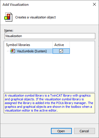
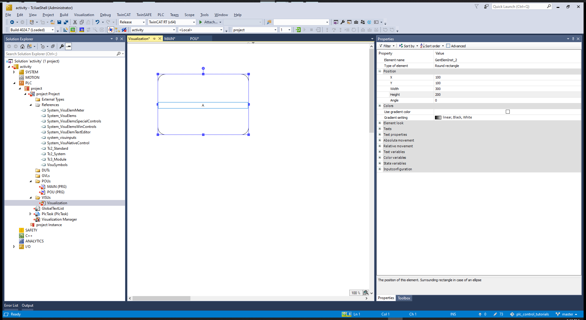
Then we can add a visualization:
Create a Rounded Rectangle, give some measures and double click in the middle to give it a sintax, in this case A button. Then we can connect the A button to the A variable.
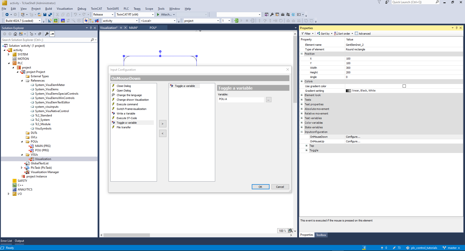
At OnMouseDown add the Toggle a variable to toggle POU.A. So now the block is connected to the input A.
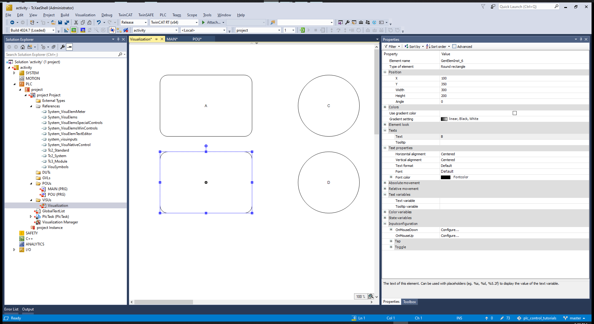
Copy and paste the button, then change the text and the variable that it toggles. And add a couple of elipses.
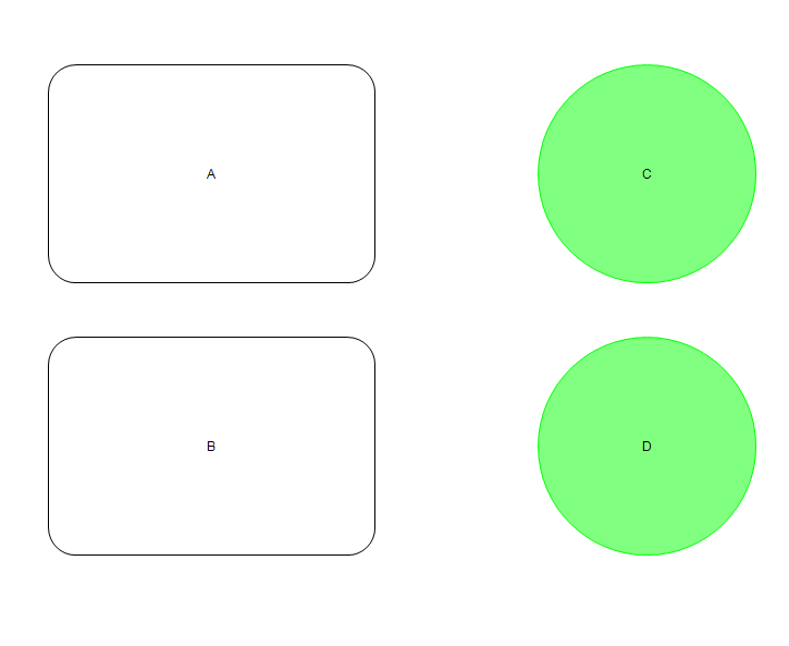
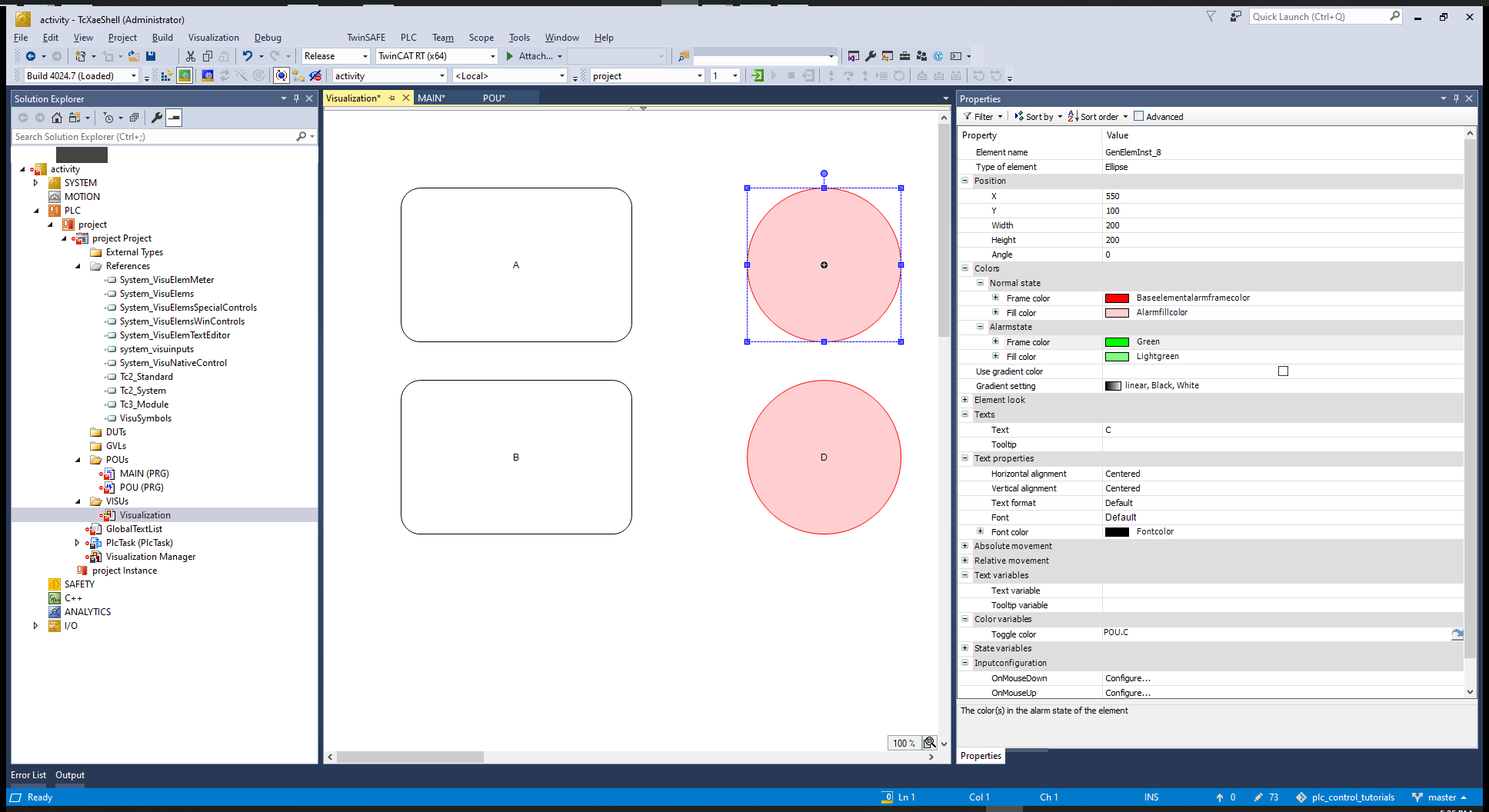
On color variables set the toggle colors. Also change the color of the button.
Build the project, activate, login to the PLC etc...
If we toggle A, after 5 s B is toggled.