# Assessment 03 - Simulation
Thiago Lima Souto - Mat.: 19044686
Professor Dr. Frazer
Masters of Engineering - Mechatronics
Massey University - 2nd semester 2019 - Auckland
Course: 282.758 – Simulation, Modelling and Optimisation Assessment: Assessment 03 – Simulation
- Analyse a system and create a model and/or simulation.
- Work individually, or in groups, to achieve a solution.
- Present the results of a simulation, modelling or optimisation task in an appropriate manner.
- Tackle an open-ended task and return the best solution within a given timeframe.
Weighting: 20%. Due Date: 11/09/2019. This is an individual assessment.
Introduction
In this assessment you are required to simulate a DC motor and design, tune, and simulate an analogue Proportional Integral Derivative (PID) controller for it.
Aims
The assessment’s aims are to:
- Become familiar with SPICE models, simulators, and simulation.
- Simulate a circuit that uses real-world models of electronic components.
Objectives
The assessment’s objectives are to:
- Run a simulation of a DC motor.
- Design and tune a PID controller for the motor.
- Capture a schematic of an analogue PID controller’s circuit in a simulator and use real-world models for the components.
- Run a simulation of the combined PID controller and DC motor.
- Validate the PID controller’s performance.
Requirements
You are required to:
- Create a simulation that achieves the assessment’s objectives.
- Write a short report detailing what you did, how, and why.
Report Assessment:
The report describes what was done, how, and why.
The report discusses the simulation task in detail.
The report discusses the tools used and how.
The report discusses the DC motor simulation, the PID controller, the captured schematic, and the combined system in detail.
The report discusses and evaluates the combined system’s results in detail.
The report’s grammar, punctuation, fluency, spelling, and language used is excellent.
# The Simulation - DC Motor Model
# Tools used
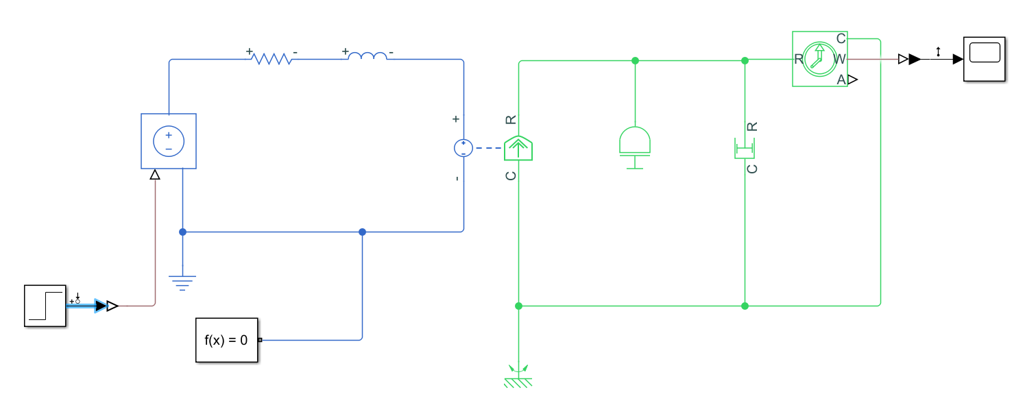
The DC motor model was built using Simulink Simscape tool, as can be seen on the figure below we have to systems (electrical and mechanical) linked by a Rotational Electromechanical Converter. The networks have different colors, the electrical system is blue and the mechanical is green.
The electrical system is composed by a resistance, an inductor, ground as well as a controlled voltage source and the simulink solver (which is necessary only for the simulation), representing the electrical model of the motor.
The mechanical part of the motor is composed by an inertia element, a rotational dumper and a ideal rotational motion sensor that will measure the angular velocity of the system.
# Why Simulink/Simscape?
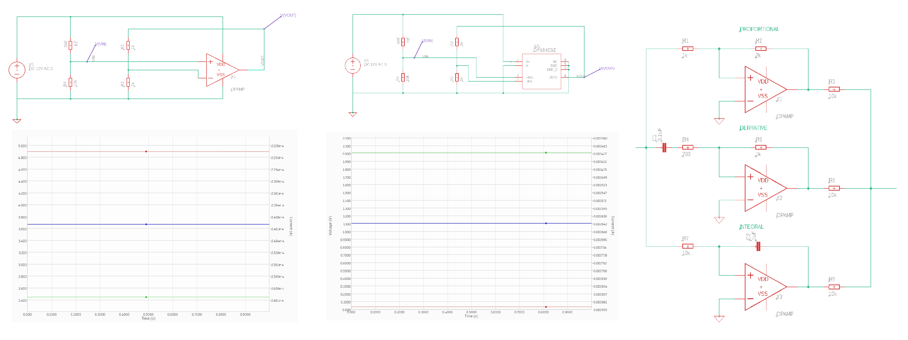
Another programs were used to solve the simulation problem, like Autodesk Eagle, although a limitation was found in regards to the mechanical modeling. Eagle is a very good software that allow the user to replace the simulation components with real components, although to simulate the mechanical part of the problem can be very difficult since electronic equivalents have to be arranged. See below the simulation on Eagle of a OpAmp using the ideal Spice model and a real component and the simulation results (virtually the same), find also a model of a PID controller including the electrical part of the DC motor.
# Finding the Transfer Function for the system in Matlab
For this purpose the system has to be linearized and this is done by entering on the net, on the beginning and at the end the Linear points (input perturbation and output measurement) then on the Control Design menu initialize the Linear analysis.
This will create a file that can be dragged to the matlab workspace, you can also test various reaction of the system on the linear analysis, It's a very powerful tool.
Finally on MAtlab we can attribute the simulation to a function and extract It's transfer function based on the space state model that is generated on the file.
The process is ordered below and exposed on the Figure.
Enter Linear Points --> Initiate Linear analysis --> Include the simulation on Matlab Workspace --> extract the transfer function.
           6.923e06
  ---------------------------
  s^2 + 3.077e04 s + 6.282e06
2
3
# Creating a Mask for the subsystem to simplify the model visualization
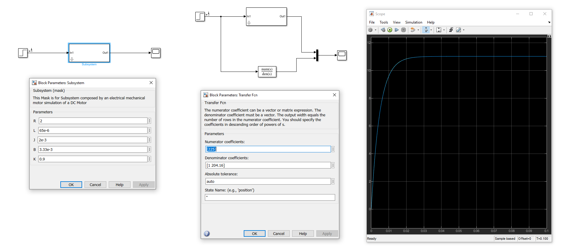
A mask was created to include the Subsystem composed by the motor electrical and mechanical simulation, and 5 parameters were used to give values to the components, R, L, J, B and K.
By comparing the transfer function founded by simulating the system with the transfer function calculated we can see that they have virtually the same result, as shown on the Figure below.
# Tunning the PID Controller manually and automatically
By tunning the PID controller manually we can achieve good results as can be seen on the figure below:
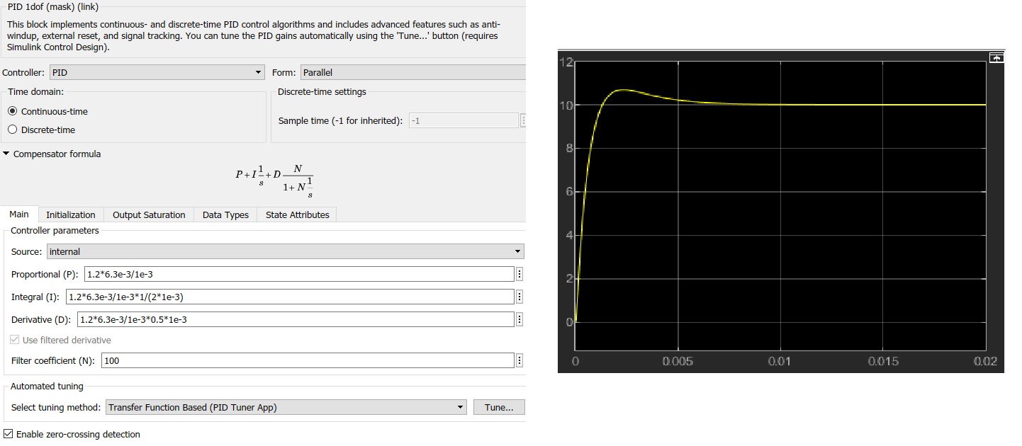
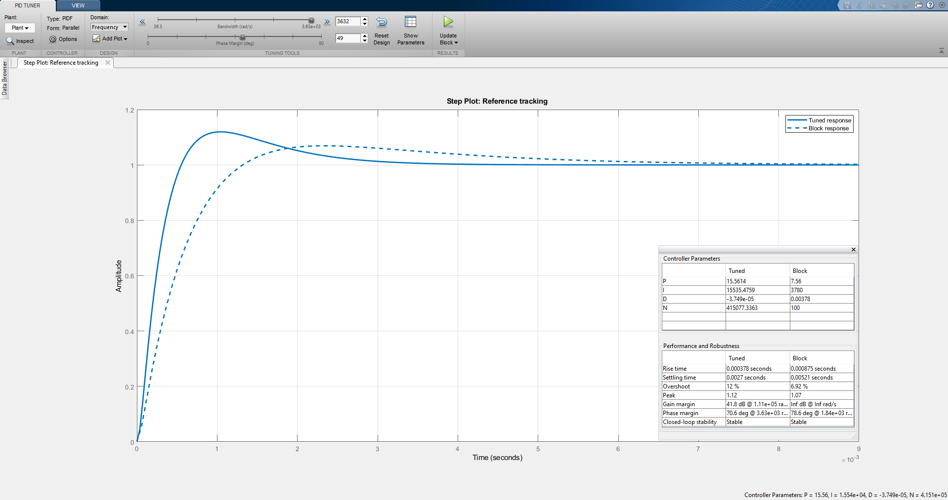
The second method is to tune the PID controller using the PID Tuner which allows you to easily meet design criteria by changing sliders of the parameters and verifying the results on Overshooting, Rise time, Settling time, Peak and more.
# The combined system’s results
By combining the electrical system and the mechanical system we were able to achieve much more trustable results with a more comprehensive approach and, why not, more confidence on the results. more confidence because on Eagle, which is an excellent electrical simulator, we could build the equivalent systems but the room for mistakes also increase. Also by using Simulink/Simscape we have the option for the PID Tuner which can be very useful to achieve design considerations.