# Mechatronics
282.778 MechatronicsEach student should take 2 hour(s) of Lecture(s) and 2 hour(s) of Lecture/Tutorial(s) per week.
# Assessments
# 1️⃣ First Class
Visit Motet museum - Transport museum
# Textbook
– Mechatronics by W. Bolton, 5th Ed. (Pearson, 2011)
https://www.amazon.com/Mechatronics-Electronic-Mechanical-Electrical-Engineering/dp/1292076682/ref=sr_1_fkmr1_2?keywords=Mechatronics+by+W.+Bolton%2C+5th+Ed.+%28Pearson%2C+2011%29&qid=1582510981&sr=8-2-fkmr1
# Definition of mechatronics:
Electrical, mechanical, control and the synergy between them.
Mechatronics is a methodology used for the optimal design of electromechanical products.
Mechatronics describes an interdisciplinary design methodology which solves primarily mechanically oriented product functions through the synergistic spatial and functional integration of mechanical, electronic, and information processing subsystems.
Mechatronics is the synergistic combination of precision mechanical engineering, electronic control and systems thinking in the design of products and manufacturing processes. It covers the integrated design of mechanical parts with an embedded control system and information processing.
# Mechatronics - Electronic control systems in mechanical and electrical engineering - Sixth Edition - William Bolton
# 1. Identify the sensor, signal conditioner and display elements in the measurement systems of
(a) a mercury-in-glass thermometer,
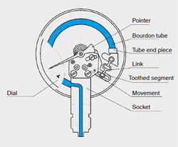
(b) a Bourdon pressure gauge.
# Reasoning:
# Measurement systems
Of particular importance in any discussion of mechatronics are measurement systems. Measurement systems can, in general, be considered to be made up of three basic elements (as illustrated in Figure 1.6).
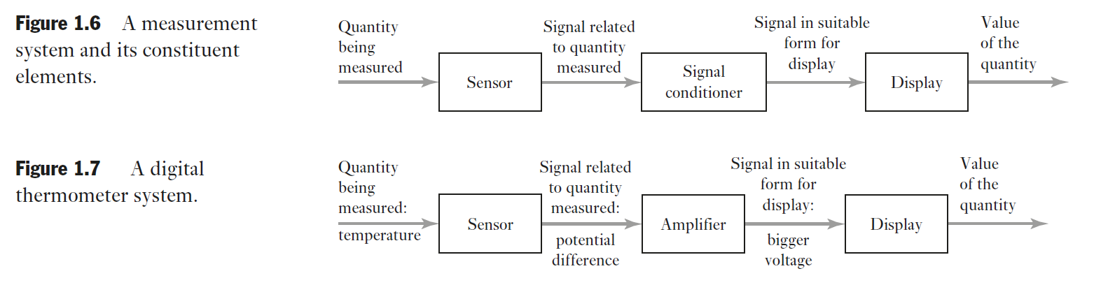
- A sensor responds to the quantity being measured by giving as its output a signal which is related to the quantity.
For example, a thermocouple is a temperature sensor. The input to the sensor is a temperature and the output is an e.m.f., which is related to the temperature value.
- A signal conditioner takes the signal from the sensor and manipulates it into a condition which is suitable either for display or, in the case of a control system, for use to exercise control.
Thus, for example, the output from a thermocouple is a rather small e.m.f. and might be fed through an amplifier to obtain a bigger signal. The amplifier is the signal conditioner.
- A display system displays the output from the signal conditioner. This might, for example, be a pointer moving across a scale or a digital readout.
As an example, consider a digital thermometer (Figure 1.7).
This has an input of temperature to a sensor, probably a semiconductor diode. The potential difference across the sensor is, at constant current, a measure of the temperature.
This potential difference is then amplified by an operational amplifier to give a voltage which can directly drive a display.
The sensor and operational amplifier may be incorporated on the same silicon chip.
Sensors are discussed in Chapter 2 and signal conditioners in Chapter 3.
Measurement systems involving all elements are discussed in Chapter 6.
# Bourdon Pressure Gauge
Bourdon tubes are radially formed tubes with an oval cross-section. The pressure of the measuring medium acts on the inside of the tube and produces a motion in the non-clamped end of the tube. This motion is the measure of the pressure and is indicated via the movement.
The C-shaped Bourdon tubes, formed into an angle of approx. 250°, can be used for pressures up to 60 bar. For higher pressures, Bourdon tubes with several superimposed windings of the same angular diameter (helical tubes) or with a spiral coil in the one plane (spiral tubes) are used.
# Answer
(a) a mercury-in-glass thermometer:
The sensor: The mercury, which is the substance that will react expanding and contracting according to the temperature.
Signal conditioner: The capillary tube, It condition the mercury to follow a path (up and down).
Display elements: The Scale lines.
(b) a Bourdon pressure gauge.
The sensor: Measuring medium on the bourdon tube.
Signal conditioner: The Movement indicates the motion .
Display elements: Pointer moving along the scale.
# 2. Explain the difference between open- and closed-loop control.
# Answer
On a open loop control there is no feedback to the system to adjust itself to new conditions. On the closed-loop control there is feedback.
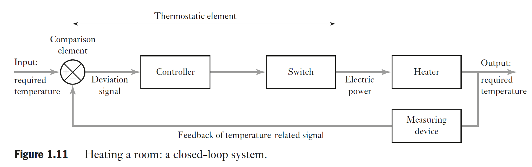
- Identify the various elements that might be present in a control system involving a thermostatically controlled electric heater.
# Answer
Controller, Switch, The very Heater, A thermometer as a measuring device and the comparison Element that will give the deviation information to the controller closing the loop.
- The automatic control system for the temperature of a bath of liquid consists of a reference voltage fed into a differential amplifier. This is connected to a relay which then switches on or off the electrical power to a heater in the liquid. Negative feedback is provided by a measurement system which feeds a voltage into the differential amplifier. Sketch a block diagram of the system and explain how the error signal is produced.
- Explain the function of a programmable logic controller.
- Explain what is meant by sequential control and illustrate your answer by an example.
- State steps that might be present in the sequential control of a dishwasher.
- Compare and contrast the traditional design of a watch with that of the mechatronics- designed product involving a microprocessor.
- Compare and contrast the control system for the domestic central heating system involving a bimetallic thermostat and that involving a microprocessor.
# Assessment 04 - Stepper Motor and Control Assignment
# 2️⃣ Lecture 02
Look for DMD technology, Digital micro-mirror device.
A DMD chip has on its surface several hundred thousand microscopic mirrors arranged in a rectangular array which correspond to the pixels in the image to be displayed. The mirrors can be individually rotated ±10-12°, to an on or off state. In the on state, light from the projector bulb is reflected into the lens making the pixel appear bright on the screen. In the off state, the light is directed elsewhere (usually onto a heatsink), making the pixel appear dark.
To produce grey scales, the mirror is toggled on and off very quickly, and the ratio of on time to off time determines the shade produced (binary pulse-width modulation). Contemporary DMD chips can produce up to 1024 shades of gray (10 bits). See Digital Light Processing for discussion of how color images are produced in DMD-based systems.
# 3️⃣ Lecture 03 - 02-03-2020
Diference of microcontrollers and CPU
- The microcontroller has "everything", interfaces, memory, ADC, DAC and the CPU just do the processing.
WARNING
Research a little more for complete answer
- Accuracy you are achieving what suppose to be achieved, precision you are doing the same thing every time.
WARNING
Voltage divider
# 4️⃣ Lecture 04 - 03-03-2020
TIP
Encoders:
On the gray code encoder only one bit change for the next number
Only one stage change from the preview number to the next number
Gray:
0000 -> 0001 -> 0011 -> 0010 -> 0110
Normal binary:
0000 -> 0001 -> 0010 -> 0011 -> 0100
# 5️⃣ Lecture 05 - 09-03-2020
Look at Op-Amps - Slide 3
TIP
Golden Rules of Op-Amps
Whatever you apply voltage on the Into the inputs It will do every effort to bring the inputs to equal level.
No current flows into the Op-Amp.
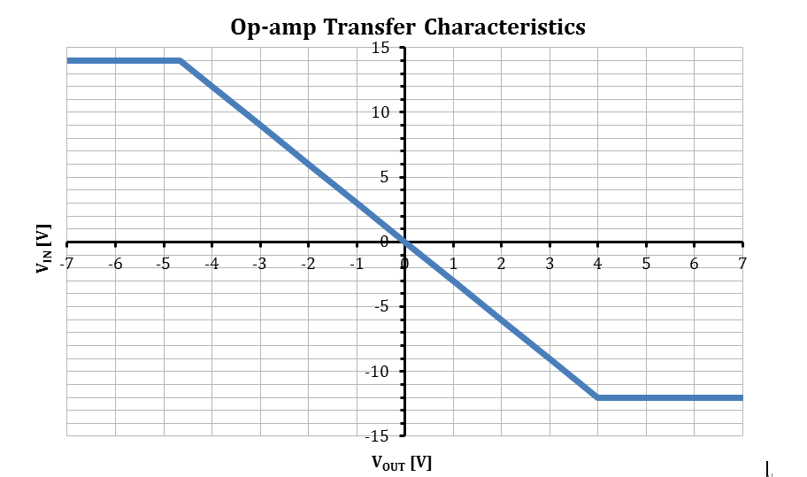
Swing of an Op-Amp - Output is never more than the power supply.
LM324 is a good Op-Amp. Check the Data Sheet. Look for the TI one.
Look for Op-Amp questions for the test.
# 6️⃣ Lecture 6 - No class
# 7️⃣ Lecture 7 - 16/03/2020
Signal Conditioning and Digital Signals
# 8️⃣ Lecture 8 - 17/03/2020
Pneumatics and Hydraulics - Start Slides for week 4 on this class.
Study the cylinder calculations
Study Control Valve calculations
# Operational Amplifier
The AmpOp is an operational block.
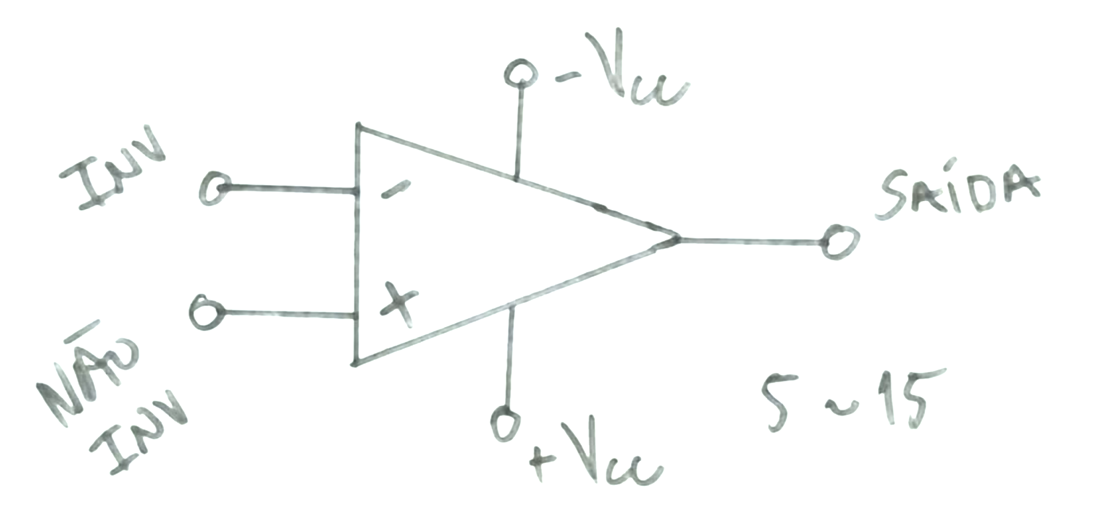
Where:
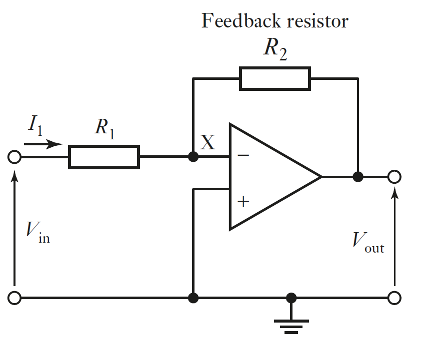
# Inverting Amplifier
The input is taken to the inverting input through a resistor R1 with the non-inverting input being connected to ground. A feedback path is provided from the output, via the resistor R2 to the inverting input.
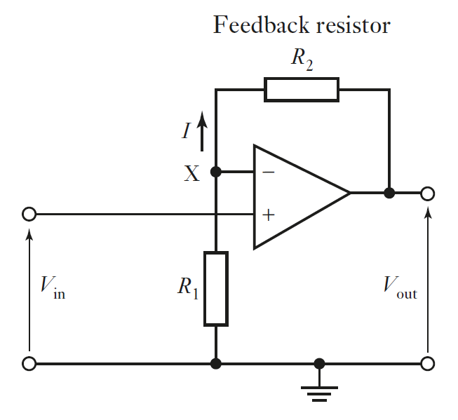
# Non-Inverting Amplifier
The output can be considered to be taken from across a potential divider circuit consisting of in series with . The voltage is then the fraction 2 of the output voltage, i.e.
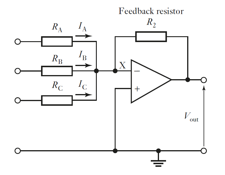
# Summing Amplifier
Consider an inverting operational amplifier circuit with the feedback being via a capacitor.
For
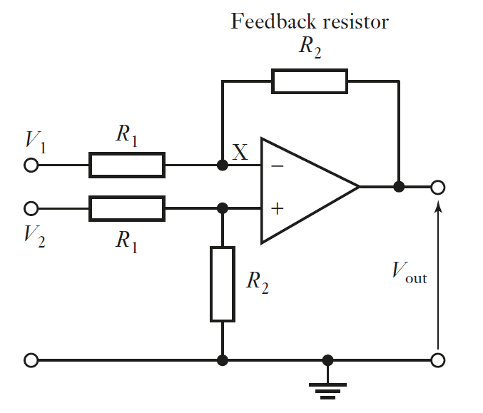
# Difference Amplifier
A difference amplifier is one that amplifies the difference between two input voltages. Figure 3.7 shows the circuit. Since there is virtually no current through the high resistance in the operational amplifier between the two input terminals, there is no potential drop and thus both the inputs X will be at the same potential. The voltage is across resistors and in series. Thus the potential at X is:
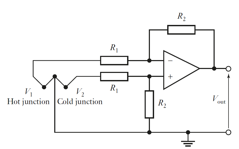
# Difference Amplifier with Thermocouple
As an illustration of the use of such a circuit with a sensor, Figure 3.8 shows it used with a thermocouple. The difference in voltage between the of the two junctions of the thermocouple is being amplified. The values of and can, for example, be chosen to give a circuit with an output of for a temperature difference between the thermocouple junctions of if such a temperature difference produces an difference between the junctions of . For the circuit we have:
Hence . Thus if we take for a resistance of then must be .
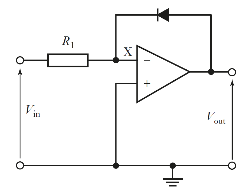
# Logarithm Amplifier
Some sensors have outputs which are non-linear. For example, the output from a thermocouple is not a perfectly linear function of the temperature difference between its junctions. A signal conditioner might then be used to linearise the output from such a sensor. This can be done using an operational amplifier circuit which is designed to have a non-linear relationship between its input and output so that when its input is non-linear, the output is linear. This is achieved by a suitable choice of component for the feedback loop.
The logarithmic amplifier shown in Figure 3.11 is an example of such a signal conditioner. The feedback loop contains a diode (or a transistor with a grounded base). The diode has a non-linear characteristic. It might be represented by , where is a constant.
Then, since the current through the feedback loop is the same as the current through the input resistance and the potential difference across the diode is $-V_{out}, we have
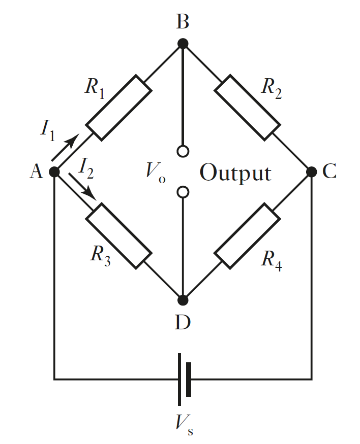
# The Wheatstone bridge
The Wheatstone bridge can be used to convert a resistance change to a voltage change.
Balanced Bridge:
# Class - Week 5 - 20/04/2020
NTN and SKF bearings are the mais producers in the industry
# First class with Frazer
Example boost 5 - multithread
boost/thread.hpp